Introduction
If you've ever wanted to make your breadboard projects more compact, you can opt to put the microcontroller directly into the breadboard - ditching the Arduino printed circuit board altogether! This kit contains all the parts required to build an Arduino Uno on a breadboard, making it easier to connect wires and decreasing the size of your project.
Identifying Parts
|
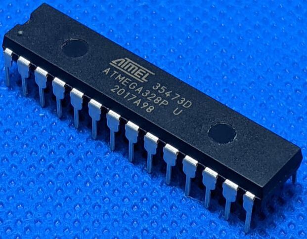
Atmega328P
The Atmega328P is the core of the Arduino, and does all the processing. All the other parts are just to support the 328P. The 328P comes in a DIP package. The metal pins are pressed into a breadboard. Most of them are the digital and analog pins you see on a normal Arduino, and the rest are supporting pins that can either be ignored, or we will connect in this guide. It is important to note that there is a dot and notch on one side of the 328P, this is the "front" of the IC. It is important to keep note of which side is the front, as this is how you know which orientation to read the pins in. The Arduino-compatible pinout can be found below. |
|
|
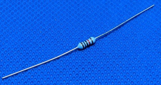
10k Resistor
The 10k ohm resistor is used to pull the reset pin high. If the reset pin of the 328P is left floating (i.e. not connected), there is a chance that it will randomly reset. However, connecting it directly to power would mean that you'd fry your programmer every time you tried to reprogram the 328P! |
|
|
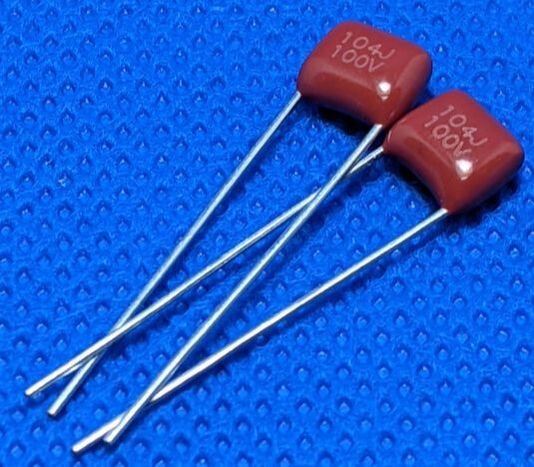
100nF Capacitor
The two included 100nF capacitors serve two different purposes. The first is a "bypass capacitor," that is used to smooth out power draw from the 328P. It is placed between power and ground, and acts like a little battery. The second is a reference capacitor. It is used to help stabilize the analog measurements of the 328P. If you are not using the analog inputs, you may be able to disregard this capacitor. |
|
|
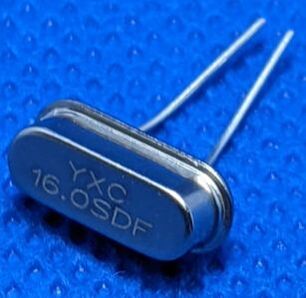
16MHz Resonator
The resonator is how the Arduino tells time. When voltage is applied to a resonator, it resonates (hence the name) at a very specific frequency. The 328P can then measure this frequency to know how much time has passed. Without this resonator, functions like delay() would not work, and the 328P would struggle with communications protocols that require precise timing, like i2C and SPI. |
|
|
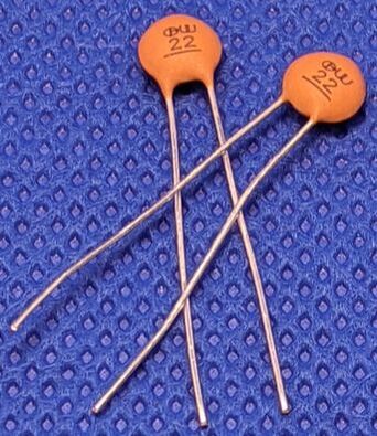
22pF Capacitors
The two 22pF capacitors are connected between the resonator and ground. These capacitors will resonate with the resonator, providing more accurate readings. |
|
Pinout
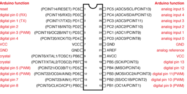
Source: Arduino.cc
Setup
Tip: The leads on the resistors, resonator, and capacitors can all be cut shorter if you want the parts to be closer to the breadboard, just make sure that they still have enough length to seat firmly in the breadboard. Also, wear safety glasses when cutting leads!
To make the 328P function as an Arduino Uno, we need to combine all of the parts. First, put the 328P onto the breadboard, making sure that the pins span across a break in the board, otherwise adjacent pins will be connected together.
Next, connect power and ground. The 328P needs 5 volts to operate. You can provide this with a breadboard power supply, USB, 3 AA batteries in series, or whatever else you have for your projects. Power connects to VCC (pin 7) and AREF (pin 21). Ground is connected to pins 8 and 22.
We'll now install the resonator. The resonator needs to connect to pins 9 and 10. The orientation does not matter, but try to keep it as close to the 328P as possible to prevent signal degradation. After that, connect a 22pF capacitor between each leg of the resonator and ground.
Then, install the two 100nF capacitors. One goes between pins 7 (VCC) and 8 (GND), as close to the 328P as possible. The other should go between AVCC (pin 20) and ground.
Finally, install the 10k resistor between pin 1 (RESET), and power.
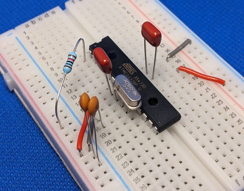
Here's an example of a fully set up Breadboard Arduino
Programming
Note: While writing and compiling code for your Breadboard Arduino, make sure to use "Arduino/Genuino Uno" as the board type.
There are 4 easy ways to upload Arduino sketches to your 328P
The first option is to swap the 328P for one already installed in an Arduino Uno. Then, just upload the code, pull out the 328P, and put it back into the breadboard.
The second option is to use a ZIF-socket programmer. These are programmers specifically designed for programming DIP micrcontrollers, like the 328P.
The third option is to use a USB to serial adapter. This will allow you to connect your 328P to your computer and upload code directly. To learn how to do this, follow the instructions on the Arduino.cc "Standalone Arduino" page. Keep in mind your 328P already has a bootloader, so no need to worry about the section on burning a new one.
The fourth and most common option is to use ICSP. To program over ICSP, you will need 6 jumper wires, and another Arduino. To program over ICSP, we will make the Arduino into a programmer, just follow the instructions on the Arduino.cc "Arduino as ISP" page. The ICSP pinout on the 328P is as follows:
- GND: Any ground
- VCC: Any VCC
- MISO: Pin 18 (Normally Digital 12)
- MOSI: Pin 17 (Normally Digital 11)
- SCK: Pin 19 (Normally Digital 13)
- Reset: Pin 1 (Make sure to connect to the pin, not on the far side of the resistor!)
Questions/Comments
If you have any questions, comments, or concerns, please feel free to contact us!