Introduction
Thank you for your purchase! I hope you will enjoy building your D6!
IMPORTANT SAFETY INFORMATION:
Only solder in a well-ventilated area while wearing safety glasses. It is strongly recommended that you solder directly in front of a soldering fume extractor to help remove any fumes from the heated solder.
While soldering, the soldering iron, solder, PCB, and electrical component may become dangerously hot. Solder on a non-flammable surface, with no flammable materials at your work space, and always be cognizant of where your soldering iron is.
The PCB in this kit uses a fiberglass core. Do not attempt to cut, scratch, or break the PCB, as it may introduce fiberglass particles into the air.
The PCB and some of the components of this kit contain lead. Do not eat or drink while handling the kit, or put the kit and/or its pieces in your mouth.
Some of the leads on these parts are sharp, be careful not to injure yourself!
Before we get started, it is best to review a few things. First, if this is your first time soldering, it may be worth reading the "Basics of Soldering" page linked below. If you want to learn more about basic PCB and electronics, you can read the "Basics of Electronics" page linked below.
Assembly
|
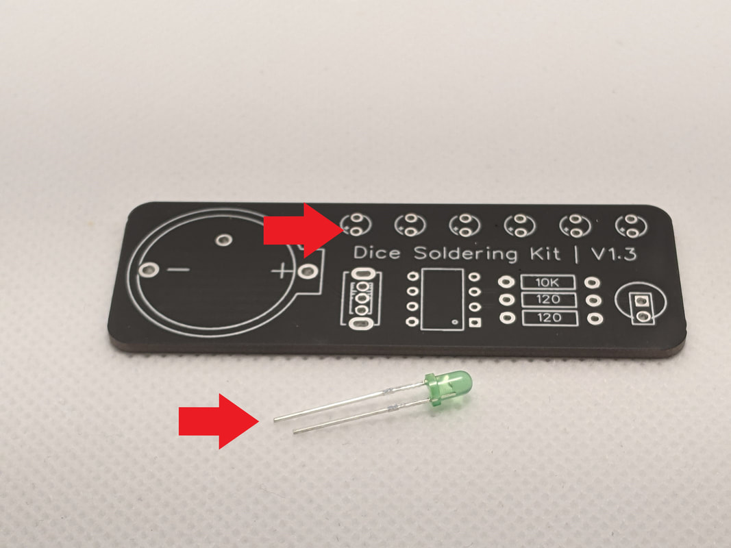
Step 1: LEDsFirst we will solder the 6 LEDs on the top of the board. The long lead of the LED needs to go through the lower hole (marked with a small plus sign).
|
|
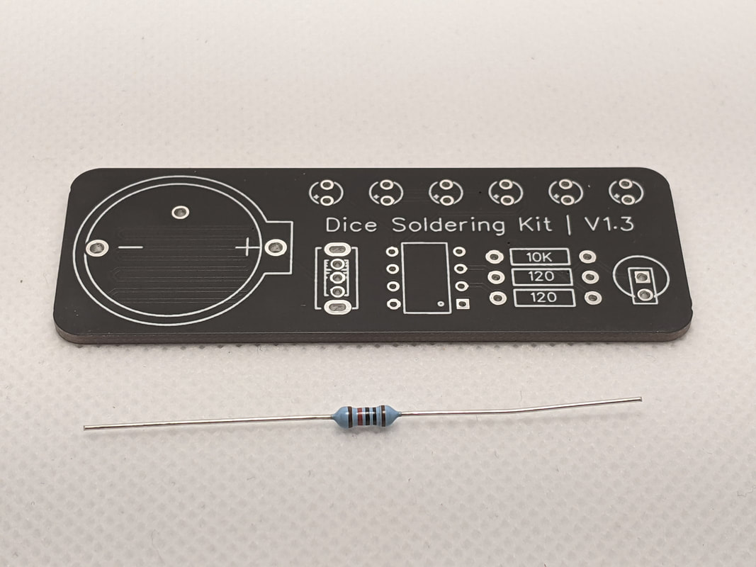
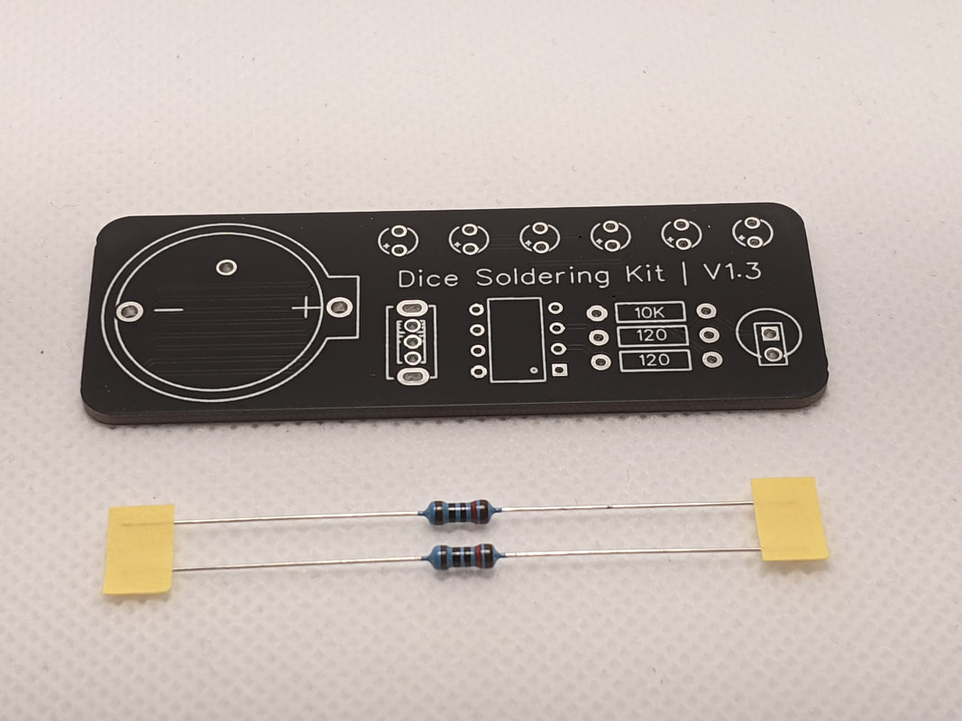
Step 2: 10k ResistorNext, we will install the 10k resistor in the spot labeled "10k" on the right of the board. Note that the 10k resistor and the 120 resistors look very similar; the 10k is the one that is not on a tape.
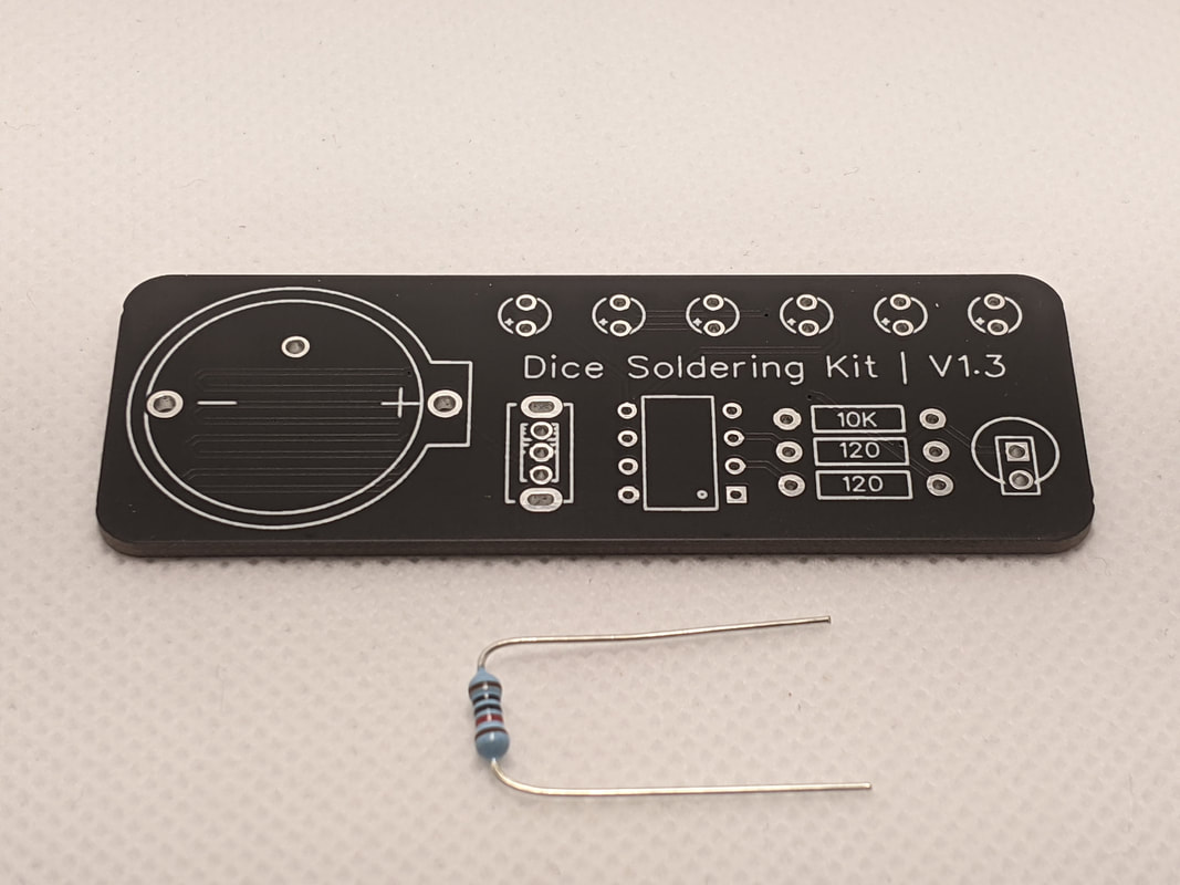
To install the resistor into the board, bend the leads and press them through the holes. The body of the resistor should be touching the board. We will install the 120 resistors the same way.
|
|
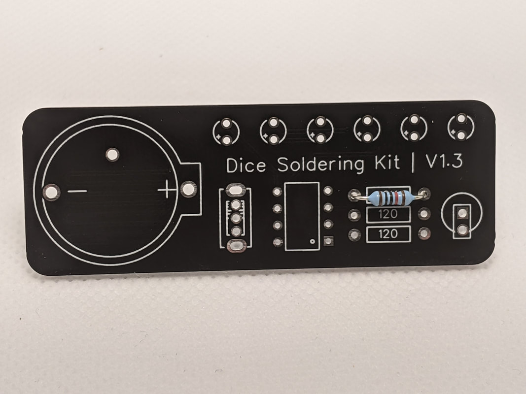
Step 3: 120 ResistorsNext, install the two 120 resistors in the spots labeled "120" underneath the 10k resistor. These are the resistors that are on a yellow tape. Install them in the same way that you did the 10k resistor.
|
|
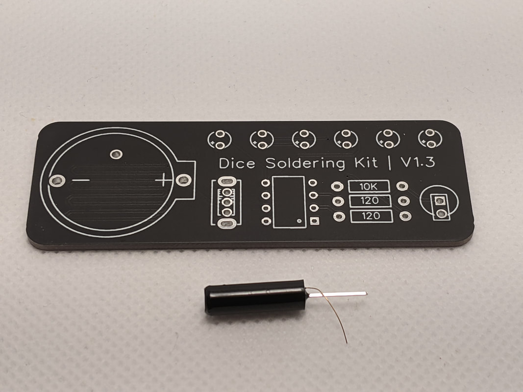
Step 4: Vibration SensorThe next step is to install the vibration sensor. The vibration center has one core lead, and one much thinner axial lead. It will be mounted in the two holes in the bottom right corner of the board. While the orientation of the part does not matter, it is generally best to put the thicker lead in the center hole.
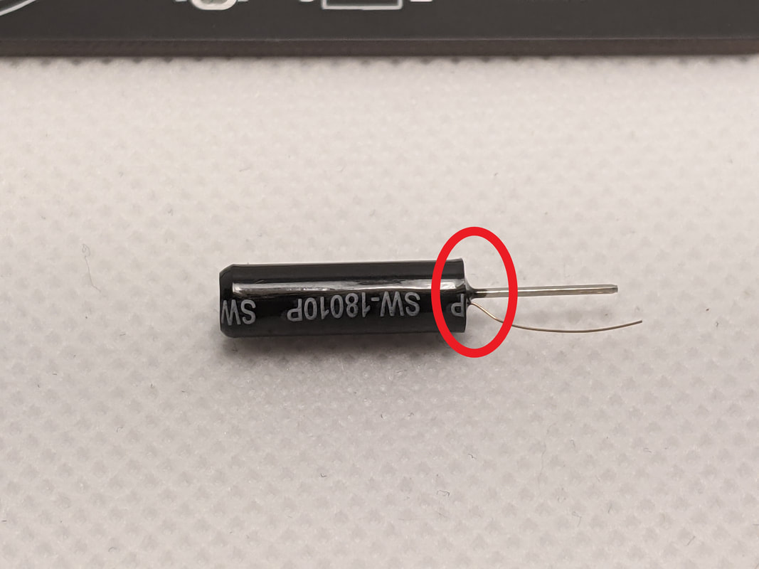
Be careful that the thin lead is not touching or wrapped around the thicker lead before soldering. There should be a noticeable gap between the two at the base.
Side note: The vibration sensor works in a very interesting way. The thick lead is just a continuous metal pole though the center of the part, and the thin lead is the end of a spring, coiled in the air surrounding the center pole. When the part is shaken, the momentum of the spring causes it to collide with the center pole, momentarily connecting the two together. In our circuit, this connects the reset pin to ground, restarting the code.
|
|
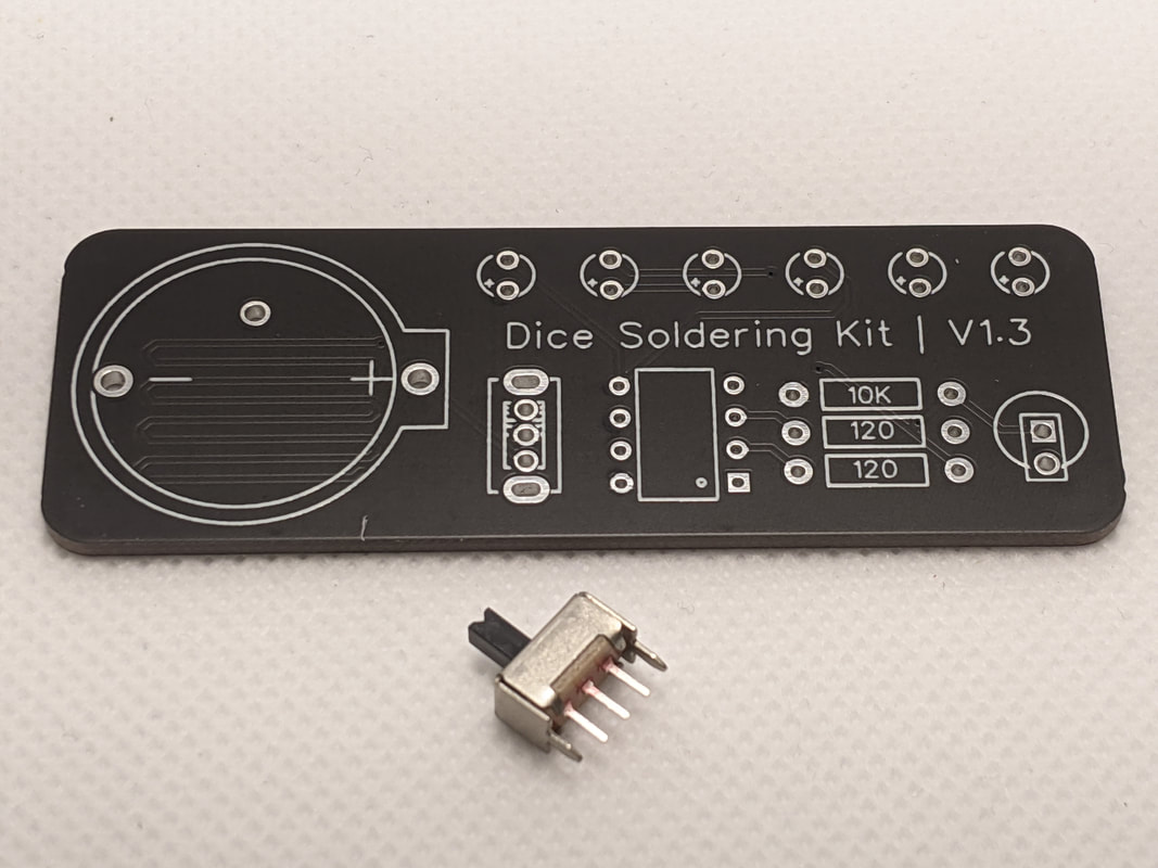
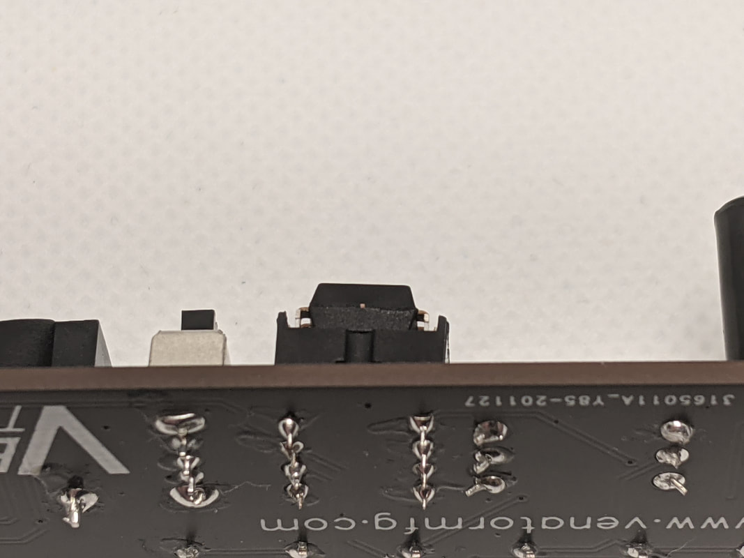
Step 5: Power SwitchNow we'll install the power switch, just below the furthest left LED. The orientation of this part does not matter.
Be careful when soldering the topmost and bottommost pins, as they are connected directly to the outer metal shell of the switch, which will make it very hot while soldering! I suggest starting with one of the smaller 3 pins in the center.
|
|
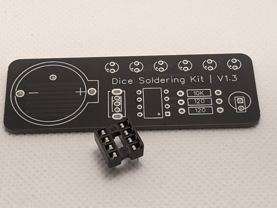
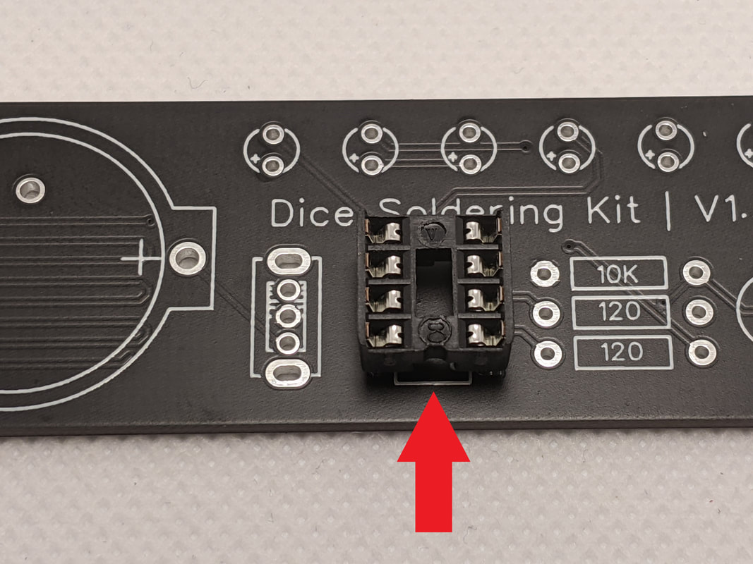
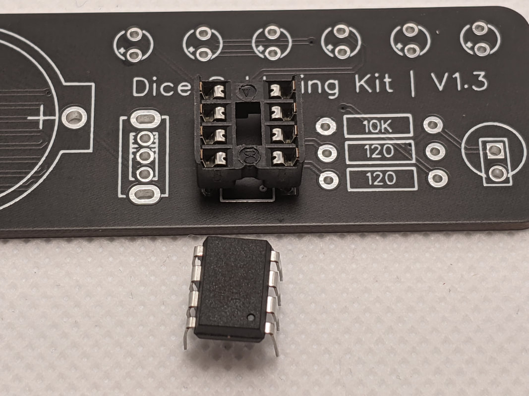
Step 6: Microcontroller SocketNext we'll install the microcontroller socket. To make it easier to remove/replace DIP components, a socket is soldered to the board, and the component is later slotted into it.
While the orientation does not matter of this part, it is best to put it with the notch down. This is used to identify the "front" of the DIP component (which does have an orientation that needs to be considered). Some DIP components will have a corresponding notch cut into them, but the AtTiny used in this project uses a dot to represent the front.
|
|
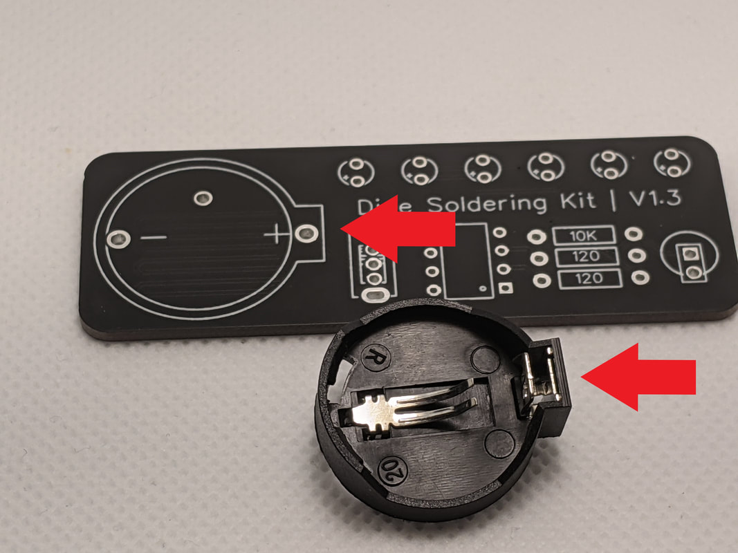
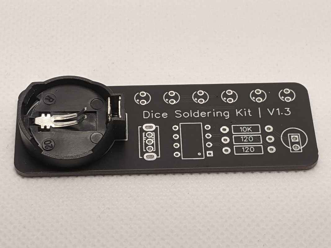
Step 7: Battery HolderThe next step is to install the battery holder. The notch on the right of the holder should correspond with the notch printed onto the board.
|
|
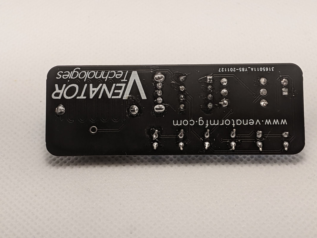
Step 8: Clean Up LeadsNow that all of the parts are soldered on, flip the board and remove all of the leads with a pair of flush cutters. Make sure to wear safety glasses, the leads will sometimes go flying!
|
|
Step 9: Install MicrocontrollerOnce the back of the board is cleaned up, you can install the microcontroller. The dot on the top represents the front of the package, which should go towards the bottom of the board.
Sometimes, the pins of a microcontroller will be splayed too wide to fit into the socket, and will need to be bent in slightly. Once all the pins are started, apply even pressure to the entirety of the top of the package to push it into the socket.
|
|
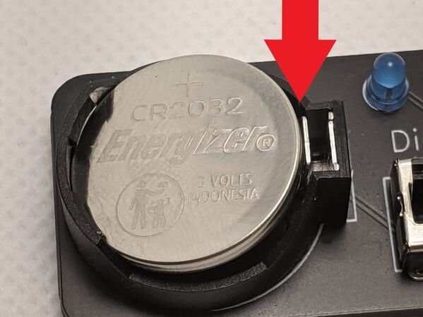
Step 10: BatteryYou can use either a CR2032 (recommended) or CR2025 coin-cell battery to power the D6.
To install the battery, plus-side up into the left of the slot. Then, press down on the right of the battery until the clip springs up on top of the battery, holding it in place.
You can now use your D6! Move the switch to the down position to turn it on, and lightly shake the board to generate a new number.
|
|
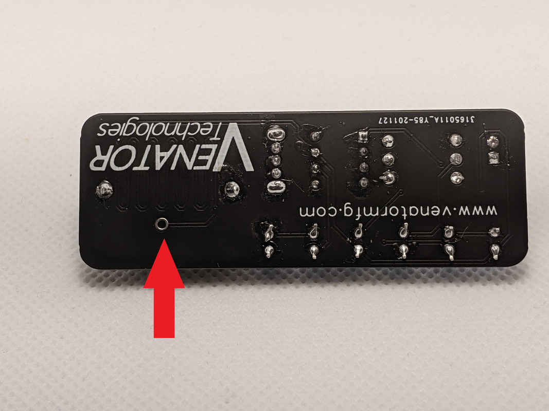
(Optional) Increasing RandomnessThe D6 uses random electromagnetic interference from the surrounding air to generate the random number. If you are in an area with very little interference, you may get consistent numbers (i.e. never rolling a 6, rolling the same number 5 times in a row, etc.). You can increase the odds of catching random electromagnetic interference by soldering a length of wire to the hole under the battery holder.
|