Introduction
Thank you for your purchase! I hope you will enjoy building your handheld game of tic tac toe!
IMPORTANT SAFETY INFORMATION:
Only solder in a well-ventilated area while wearing safety glasses. It is strongly recommended that you solder directly in front of a soldering fume extractor to help remove any fumes from the heated solder.
While soldering, the soldering iron, solder, PCB, and electrical component may become dangerously hot. Solder on a non-flammable surface, with no flammable materials at your work space, and always be cognizant of where your soldering iron is.
The PCB in this kit uses a fiberglass core. Do not attempt to cut, scratch, or break the PCB, as it may introduce fiberglass particles into the air.
The PCB and some of the components of this kit contain lead. Do not eat or drink while handling the kit, or put the kit and/or its pieces in your mouth.
Some of the leads on these parts are sharp, be careful not to injure yourself!
Before we get started, it is best to review a few things. First, if this is your first time soldering, it may be worth reading the "Basics of Soldering" page linked below. If you want to learn more about basic PCB and electronics, you can read the "Basics of Electronics" page linked below.
Assembly
|
|
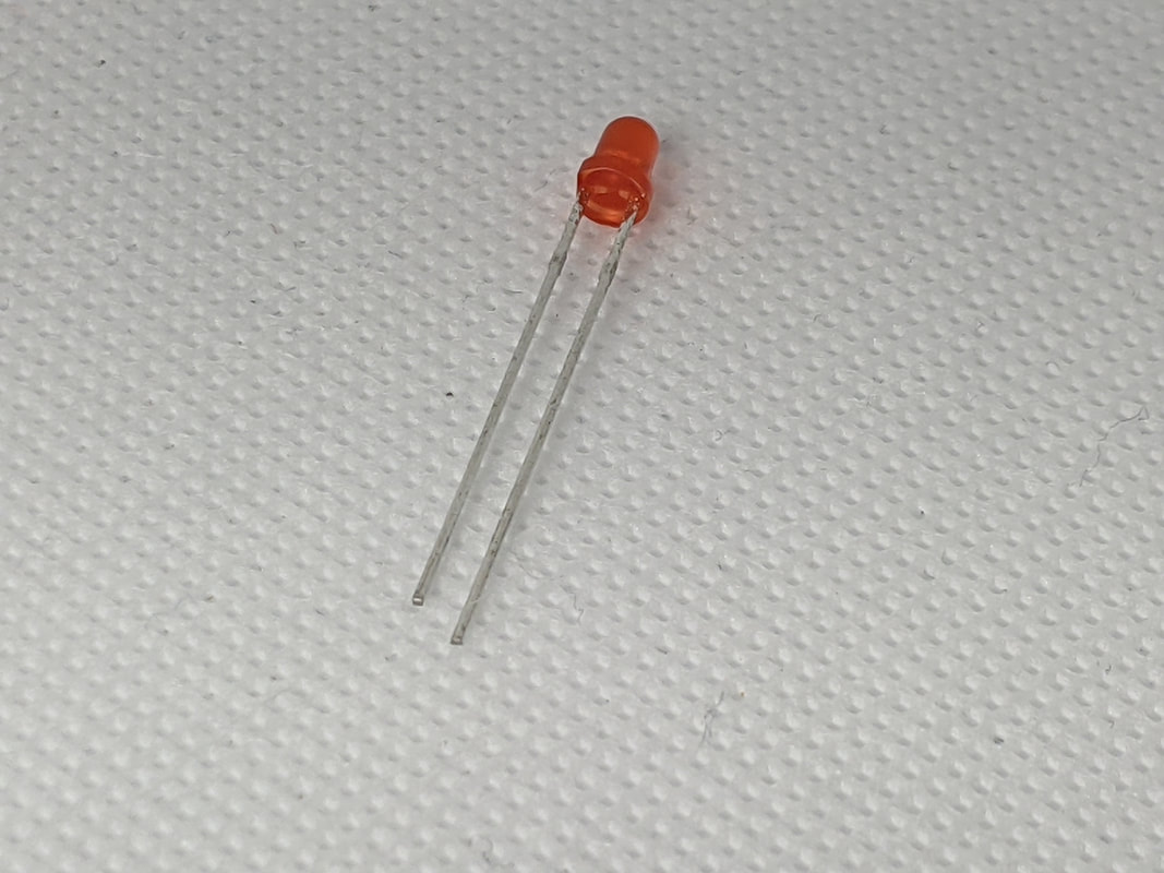
Step 1: LEDsInstall the 3mm LEDs of your choice. It is suggested to use 2 different colors, with the corners being one color, and the centers being another. When installing the LEDs, make sure that the longer lead goes into the hole with a "+" next to it.
|
|
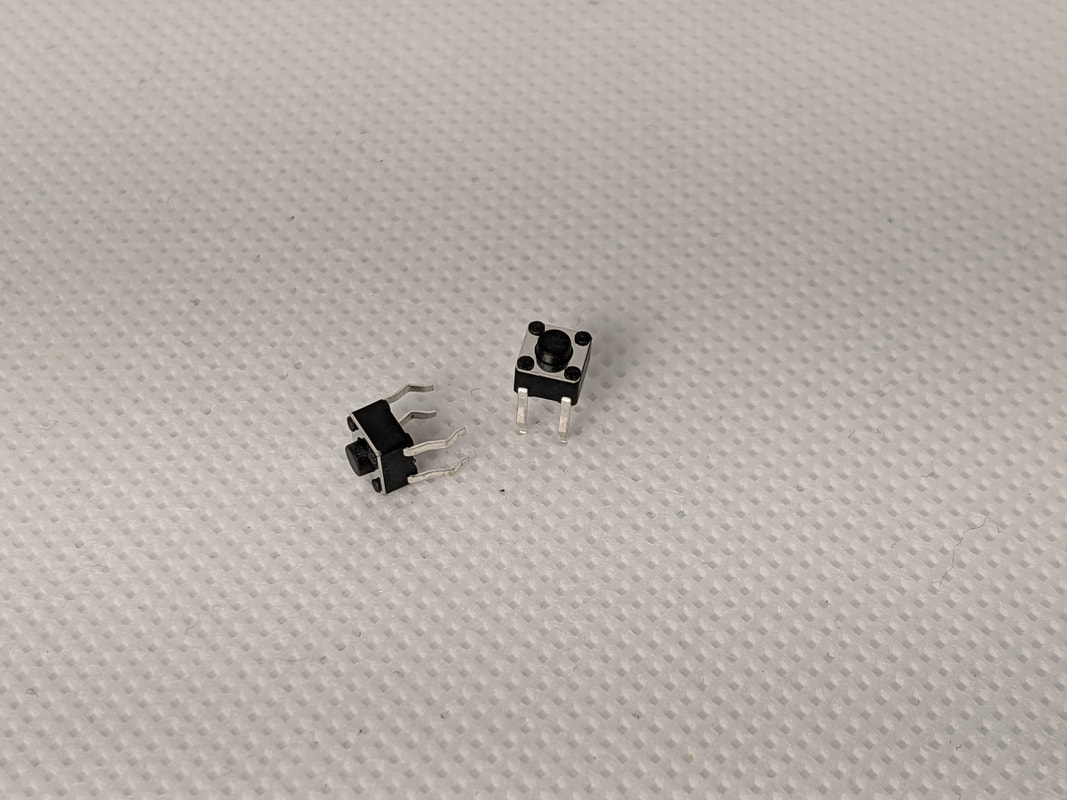
Step 2: ButtonsThere are 10 buttons on the PCB: 9 on the game pad, and 1 at the bottom (labeled "reset"). The orientation of the buttons do not matter.
|
|
|
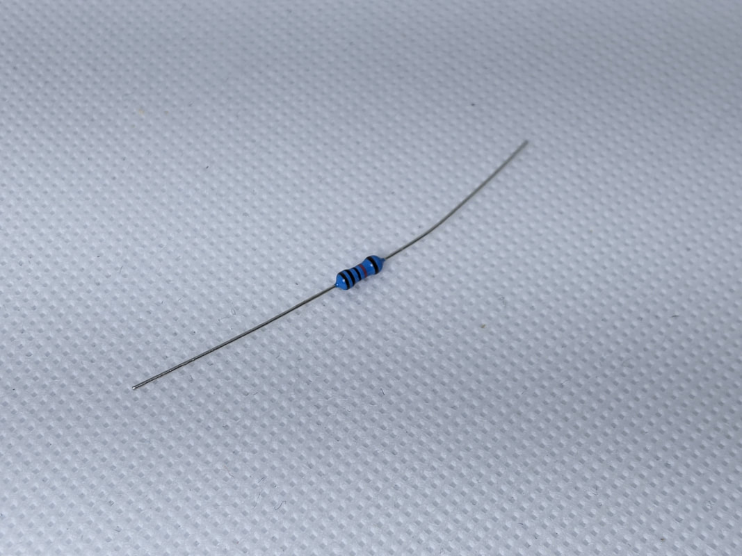
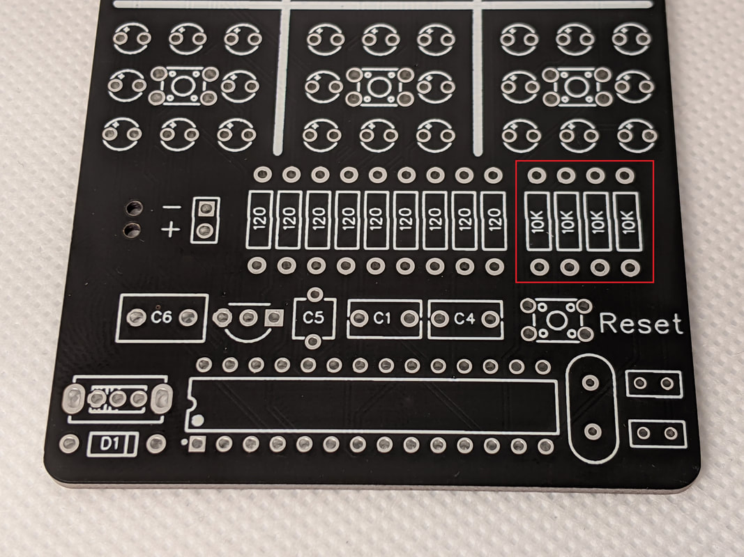
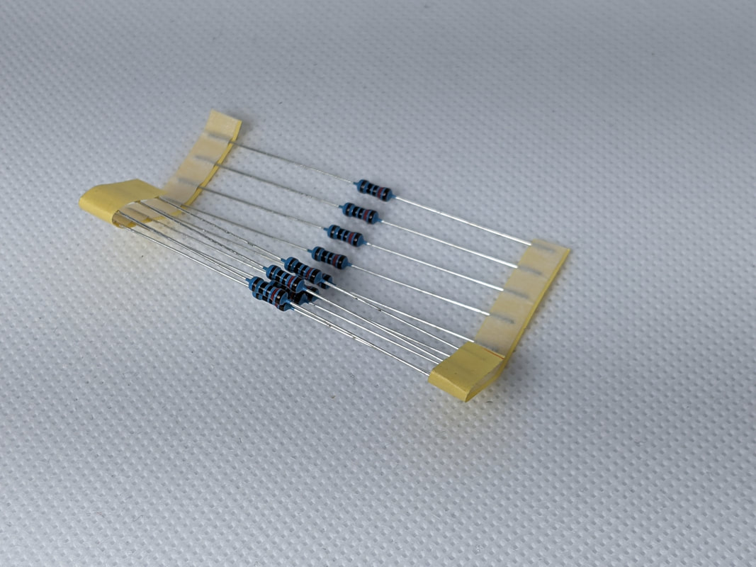
Step 3: 10k ResistorsInstall the 4 10k pull-up resistors on the board. They go on the bottom left of the board, in the spots labeled "10k." The 10k resistors are the ones that are not on a tape in the kit.
To install the resistor into the board, bend the leads and press them through the holes. The body of the resistor should be touching the board. We will install the 120 resistors the same way.
|
|
|
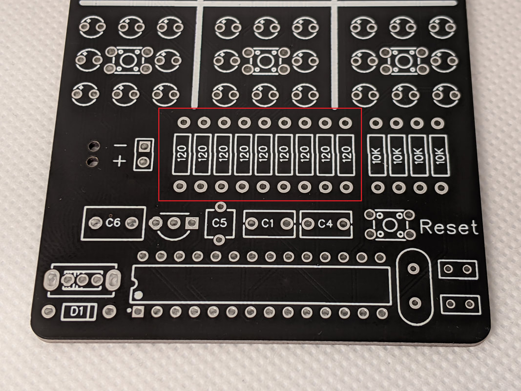
Step 4: 120 ResistorInstall the 120 ohm resistors next. They fill the remaining spots along the row in the center of the board. The 120 ohm resistors are the ones that come on a tape. Be careful! They look very similar to the 10k ones.
|
|
|
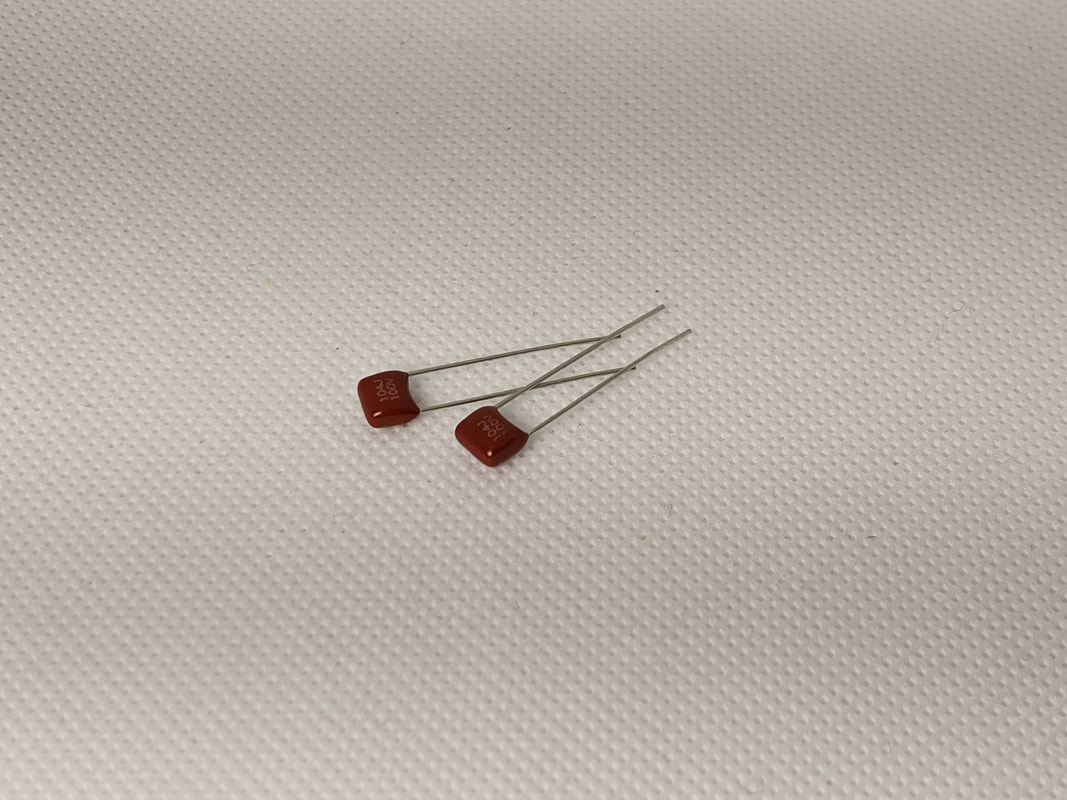
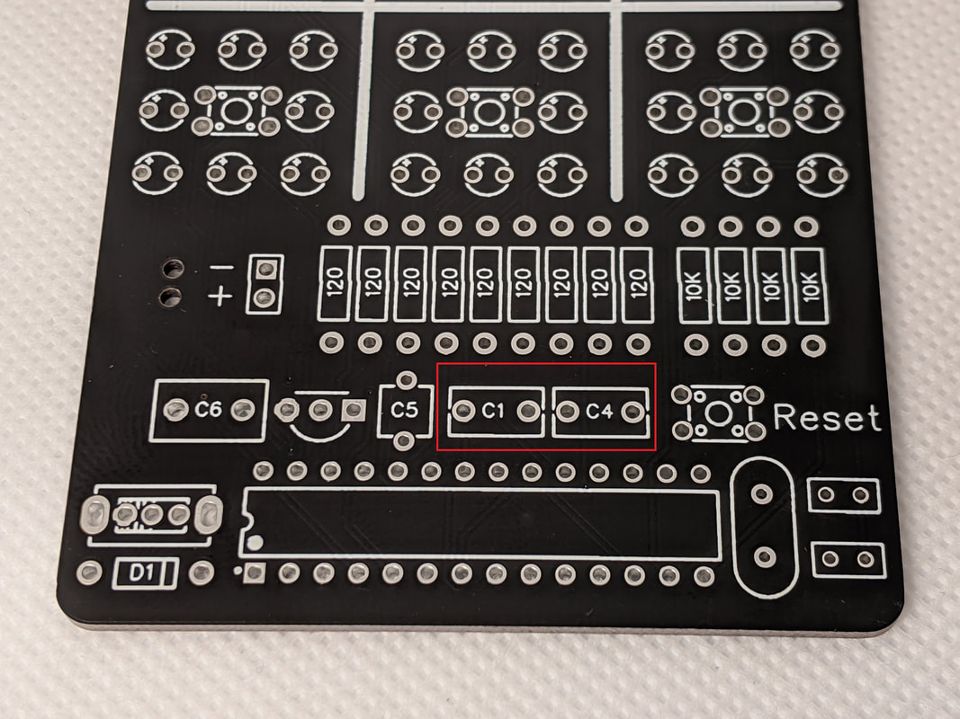
Step 5: Microcontroller CapacitorsThe microcontroller requires 2 capacitors to operate properly, these are the large burgundy rectangles in the kit. Install them in the spots labeled "C1" and "C4" on the board. Their orientation does not matter.
|
|
|
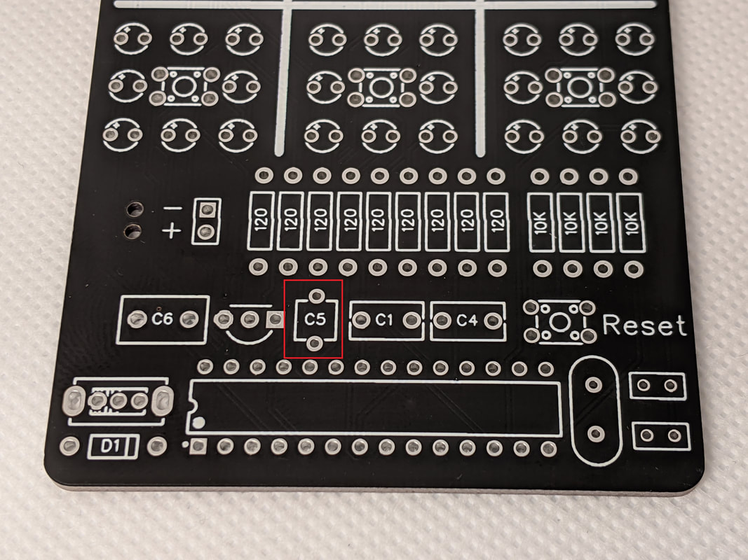
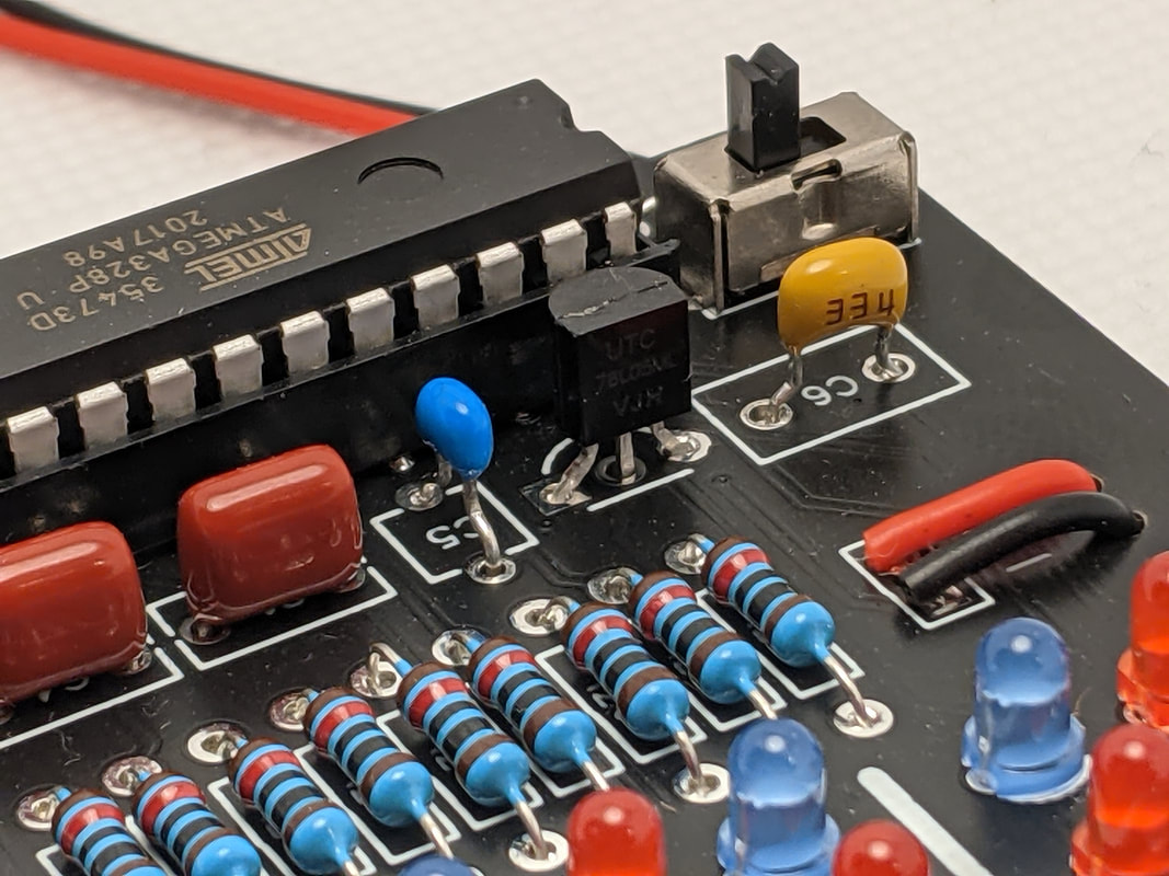
Step 6: 100nF Regulator CapacitorTo the left of the microcontroller capacitor, labeled "C5," is the regulator's 100nF capacitor. This is the small blue component with 2 leads. When installed correctly, the parts for the regulator will all sit above the board slightly.
|
|
|
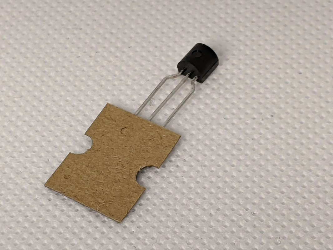
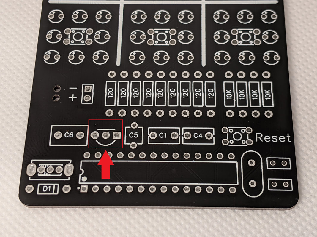
Step 7: Voltage RegulatorThe voltage regulator is the black semicircle component with 3 leads. Make sure that the curved face of the component aligns with the curve on the silkscreen before soldering!
|
|
|
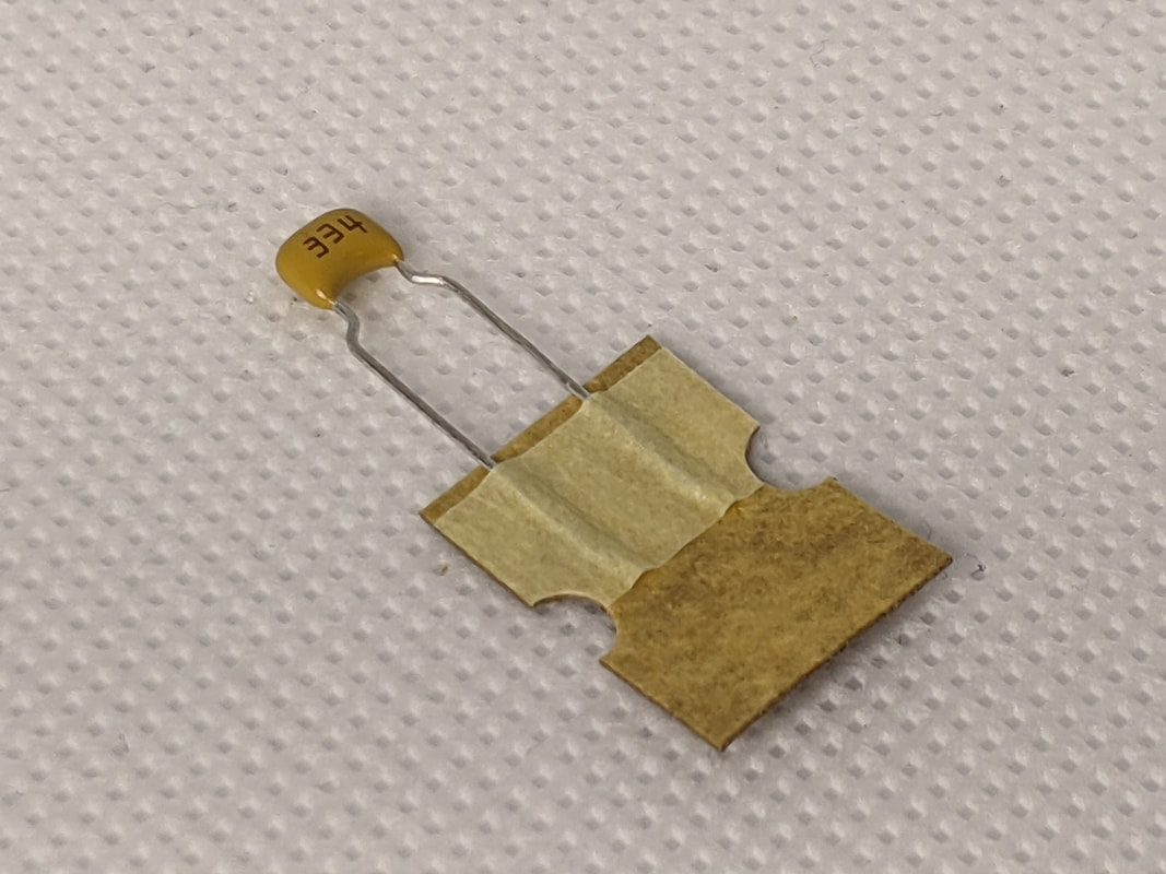
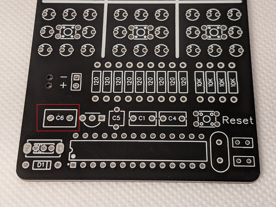
Step 8: 330nF CapacitorNext, install the beige 330nF capacitor to the left of the voltage regulator. The orientation of the component does not matter.
|
|
|
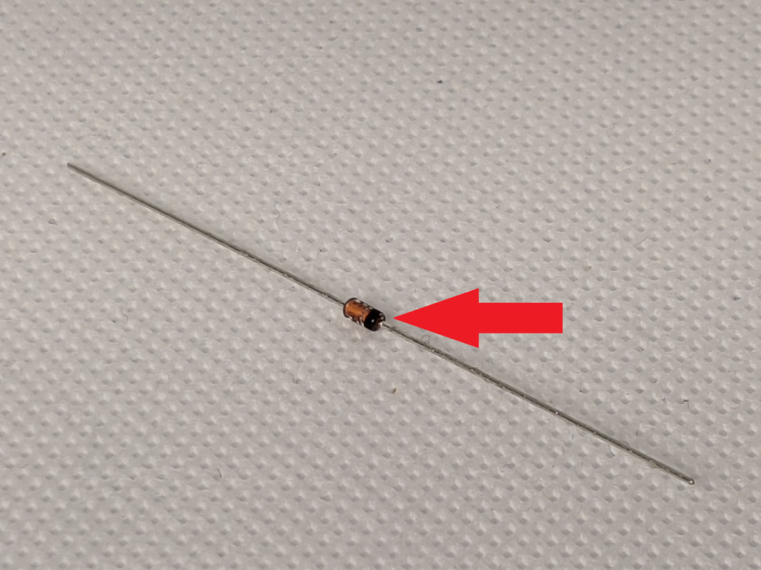
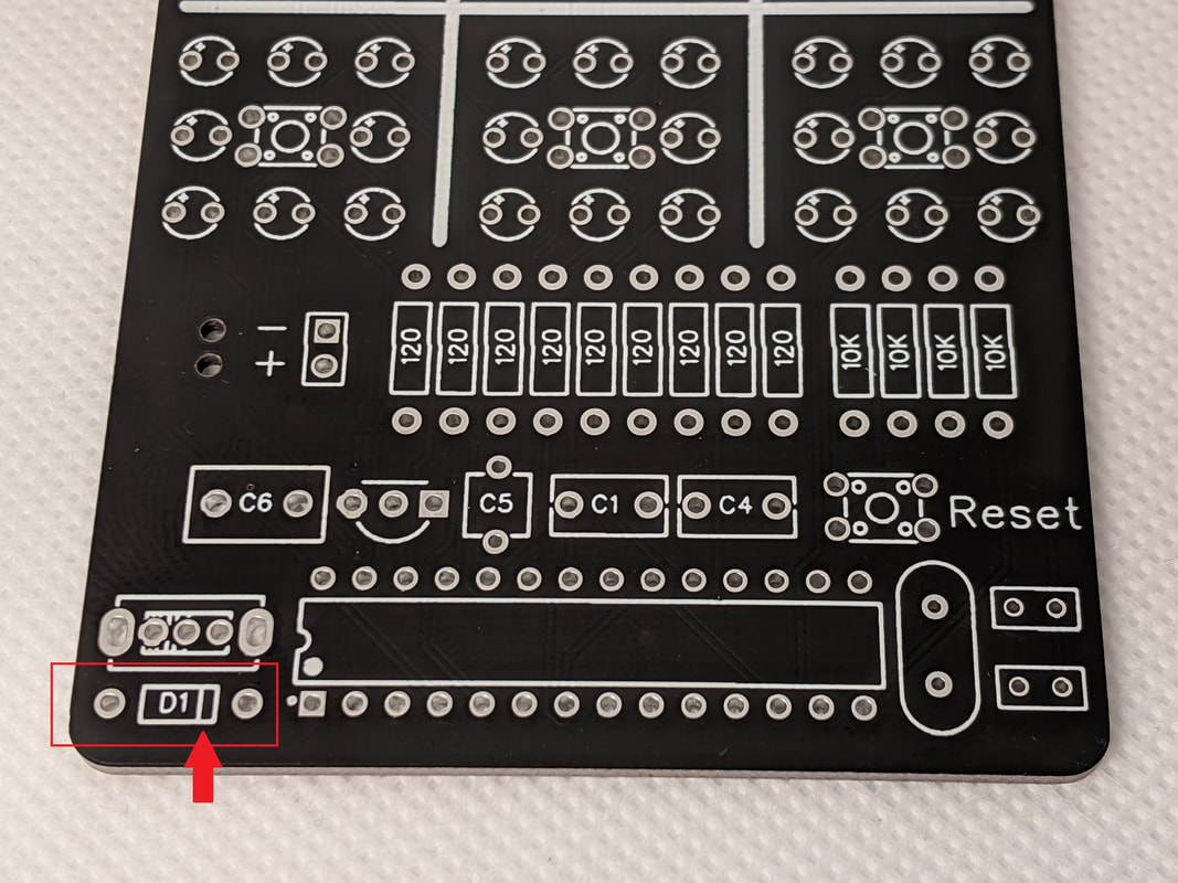
Step 9: Battery DiodeInstall the battery diode in the bottom left corner of the board. The diode's orientation is very important! Make sure that the black bar on the body of the diode is lined up with the bar on the silkscreen.
|
|
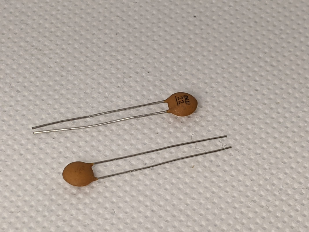
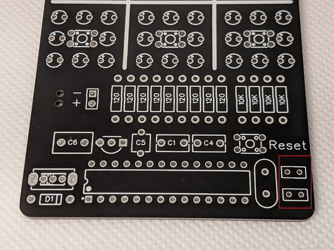
Step 10: Resonator CapacitorTo stabilize the resonator's output, two small capacitors are in parallel with it. These are the tan circular components, and they go in the two spots in the bottom right corner of the board.
|
|
|
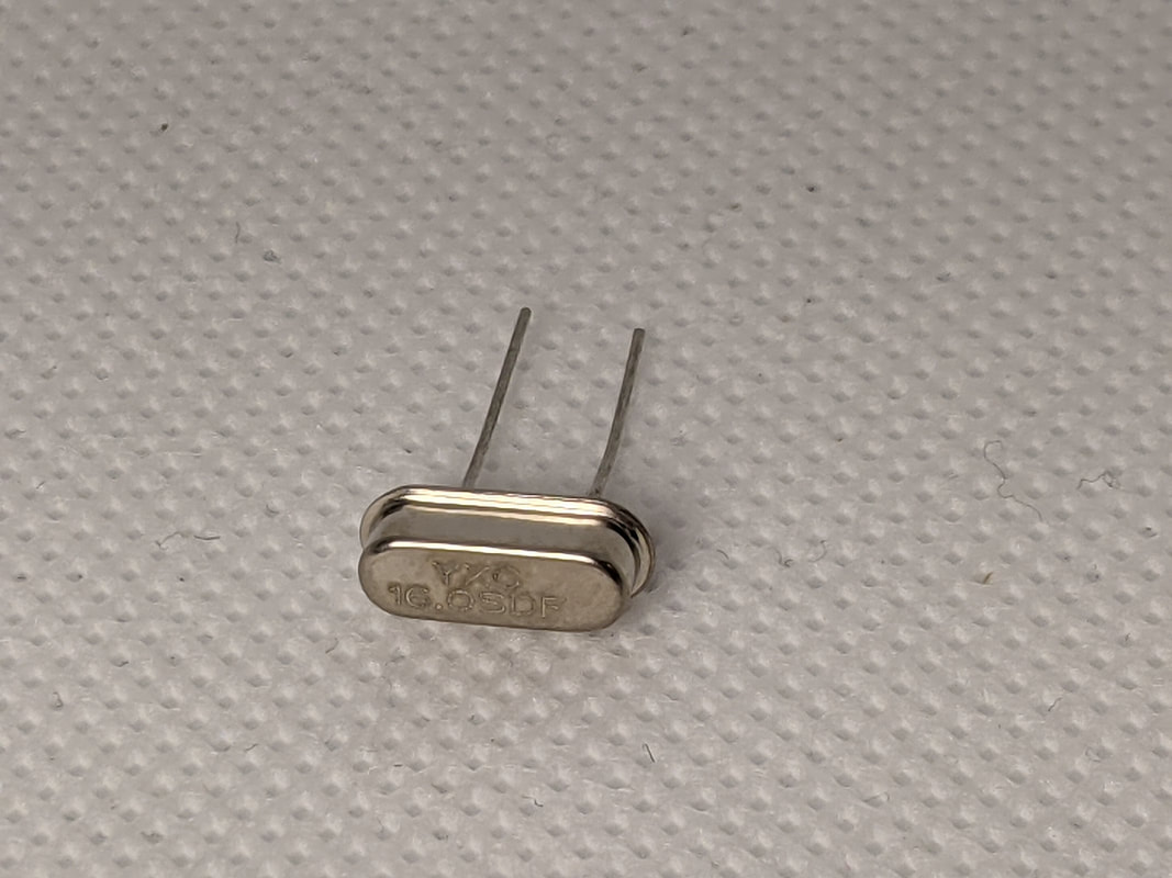
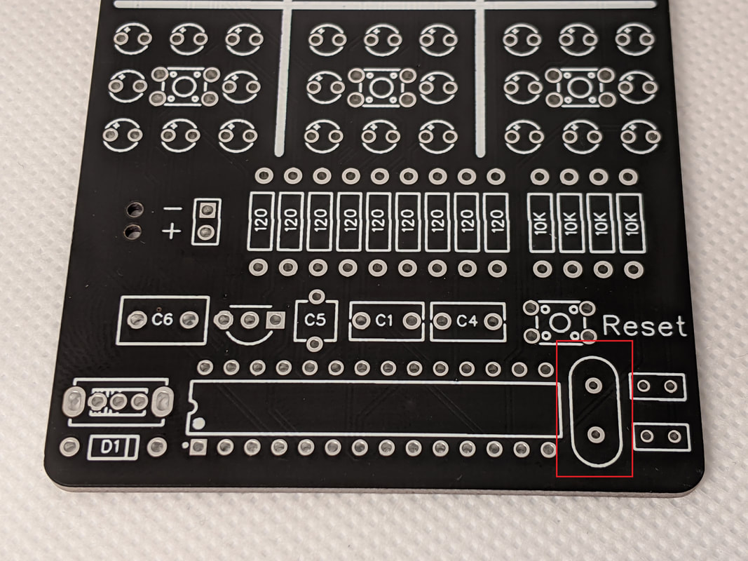
Step 11: ResonatorThe resonator helps the microcontroller time its operations precisely. The resonator is the silver component with curved ends. It goes to the left of the resonator capacitors from the previous step.
|
|
|
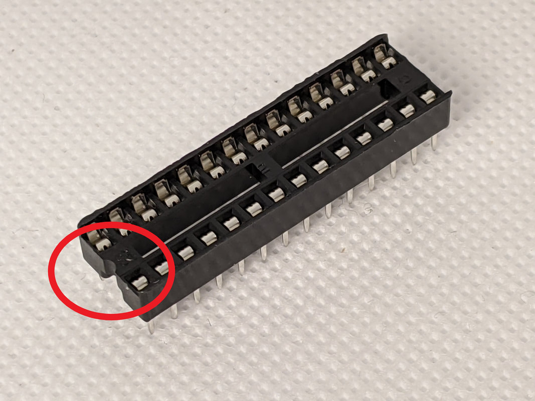
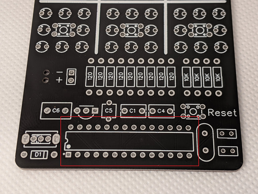
Step 12: Microcontroller SocketThe microcontroller socket goes in the bottom center of the board. There is a small notch cut on one side, that should go to the left. This is not important from an electronics standpoint, but is used as a reference to align the microcontroller properly.
|
|
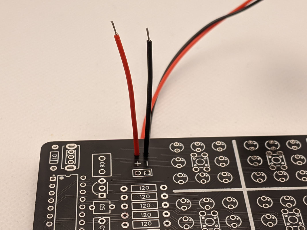
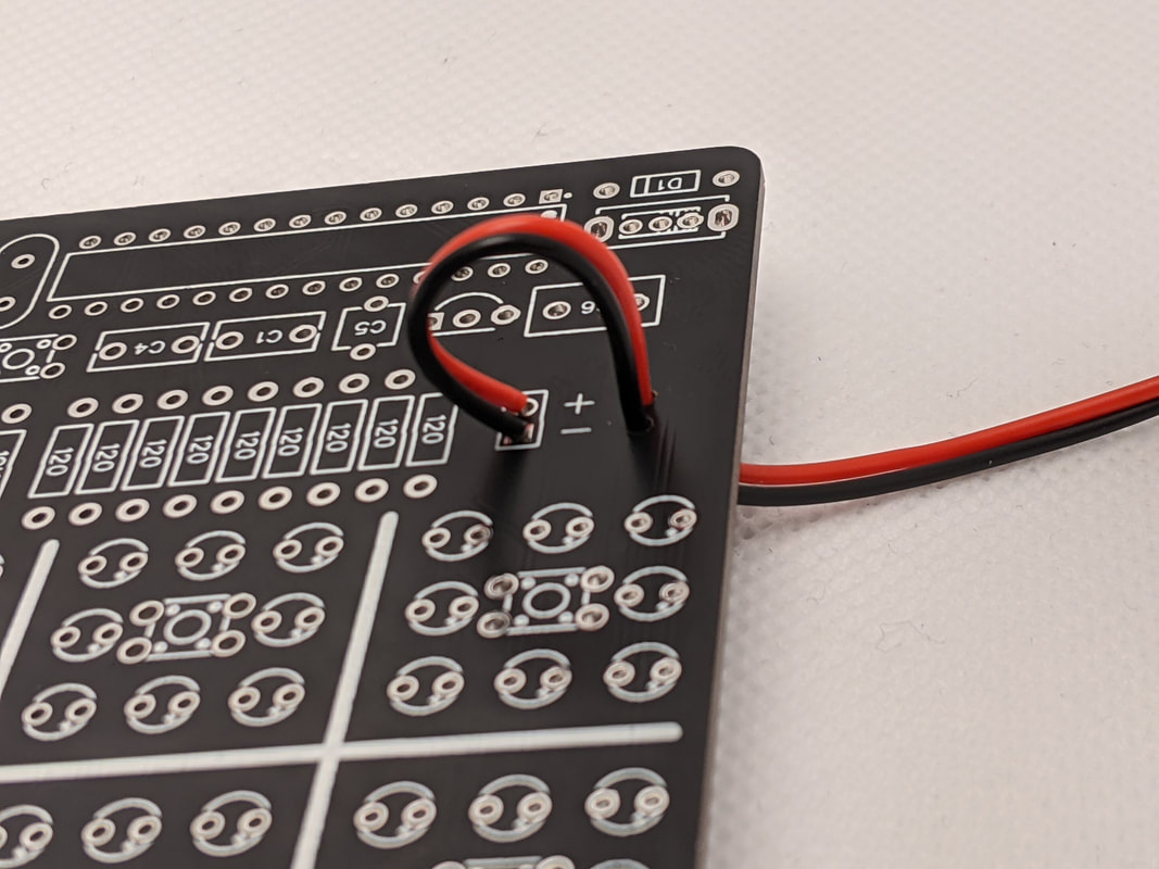
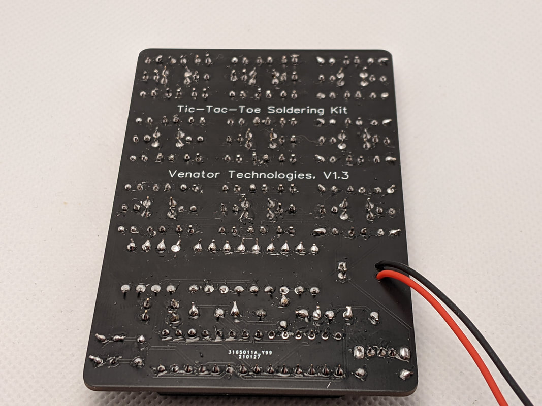
Step 13: 9V ClipInstall the 9V battery clip from the back of the board. Push the wires up through the holes on the left, with the red (power) one being the lower one. Once they are through, bend them over and solder them into the two holes above the regulator. Once soldered, pull the wires taught.

|
|
|
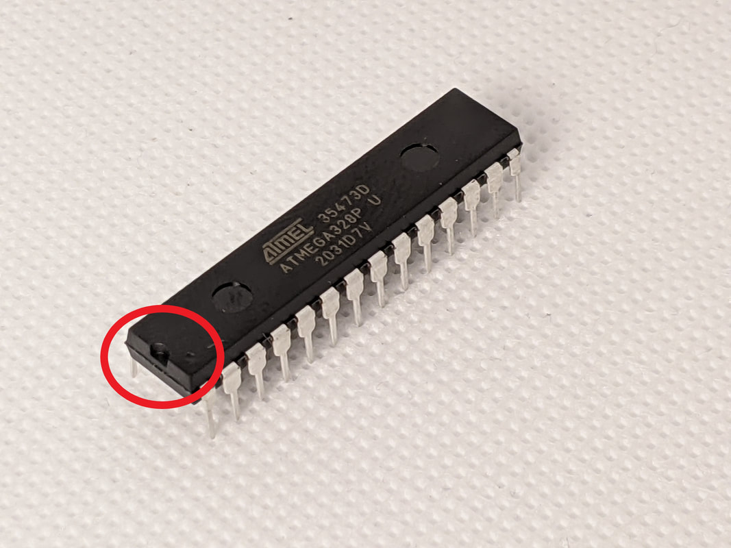
Step 14: Install MicrocontrollerFinally, install the microcontroller in the socket. The notch on the top of the microcontroller should go on the right of the socket.
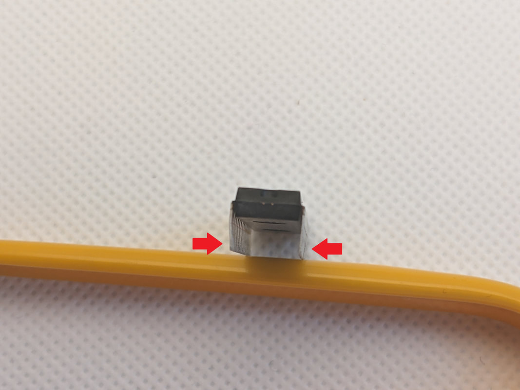
Sometimes, the microcontroller pins are splayed a bit too far out to fit into the socket. If this is the case, rest it on a table and apply slow, even pressure to the other side's pins to bend them square.
Once the pins are aligned, apply equal pressure to the top until the microcontroller descends into the socket.
|
|
Step 15: Leads CleanupFlip the board over and cut the leads extending out of the bottom. Make sure to wear safety glasses, in case they go flying!
|
|
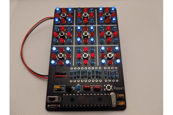
Complete!Your kit is now complete! Install a 9 volt battery, and flip the switch to turn it on!
|