Installing the Atmega 328P
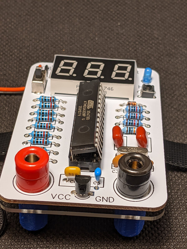
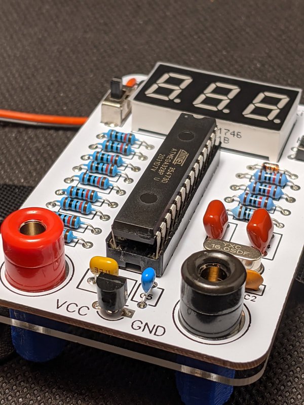
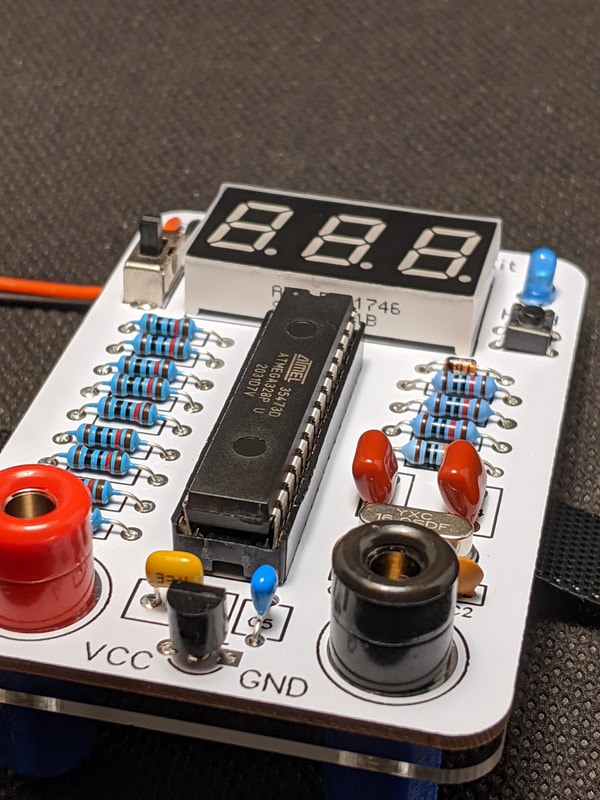
The Atmega 328P is the heart of the voltmeter. It is already programmed, so everything is ready to go once you finish soldering. To install the 328P, first identify the "front" of the DIP package. The front of the package can be identified by the notch and dot on the top of the package. The front of the DIP should go where the notch in the DIP socket on the PCB is.
Line up the pins of the DIP up with the socket. Sometimes, the pins on a DIP package are splayed out too far to fit into a normal socket. To fix this, lay the DIP down on a table so all the pins are flat against it. Then, apply a small amount of pressure slowly to the plastic package of the DIP, until the pins bend slightly at the top, nearest the plastic. Repeat the process for the pins on the other side, and continue this process until the pins slide straight into the start of the slot. Once everything is aligned, apply equal pressure to both sides of the IC to push it into the slot straight.
|
|
|
Installing + Securing the Battery
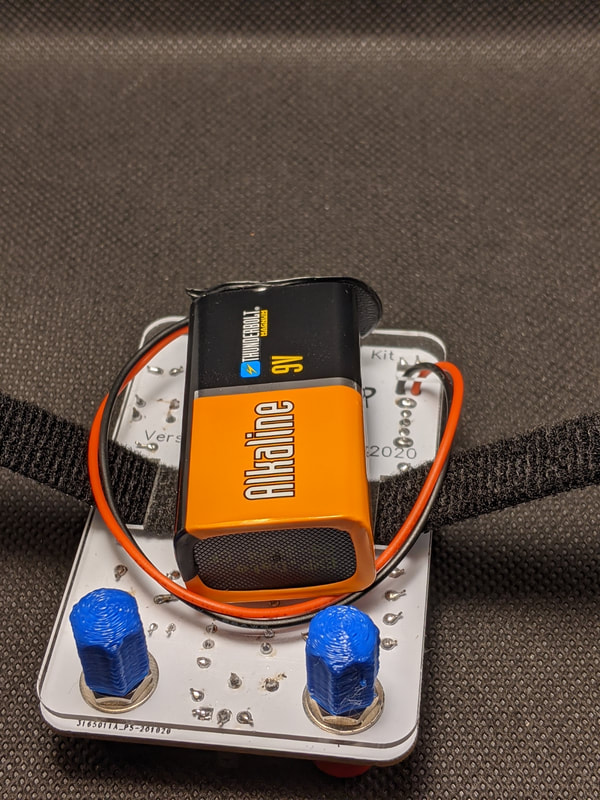
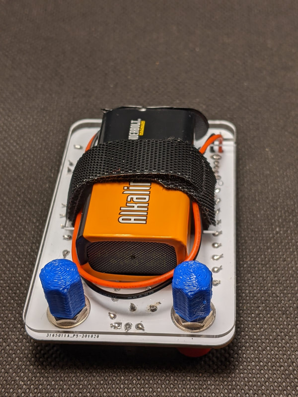
Before installing the battery, make sure the switch is in the off (down) position. Connect the 9-volt battery to the battery clip, and orient it as shown in the image below. If the wires of your battery clip are too long, loop them around behind the battery, or you can desolder them and trim them shorter. Then, close and secure the velcro strap over top of the battery. It may take some fine adjustment of the positioning of the velcro to get everything to fit together perfectly. The battery should be secured well enough that you can hold the voltmeter vertically without it falling out.
If you plan on frequently using the voltmeter while it is not sitting on a table, it is recommended to put a small piece of rubber tape or double-sided tape behind the battery so that it does not slide or move around.
|
|
Before Powering the Voltmeter...
Always be cognizant of where the voltmeter and its leads are. You do not want to put the voltmeter down on a conductive surface, or let the leads touch the voltmeter. Either of these could cause a short, which could damage or destroy the voltmeter.
Do not use the voltmeter to measure voltages above 24 volts. While, in theory, the circuitry could handle up to 50 volts, it is dangerous to have higher voltages running through an exposed device like this.
Do not measure AC or negative voltage with the meter. While the odds of either causing damage are low, it is still a risk that should be avoided. Plus, the meter will just read 0.00, so there is not much point.
Using the Voltmeter
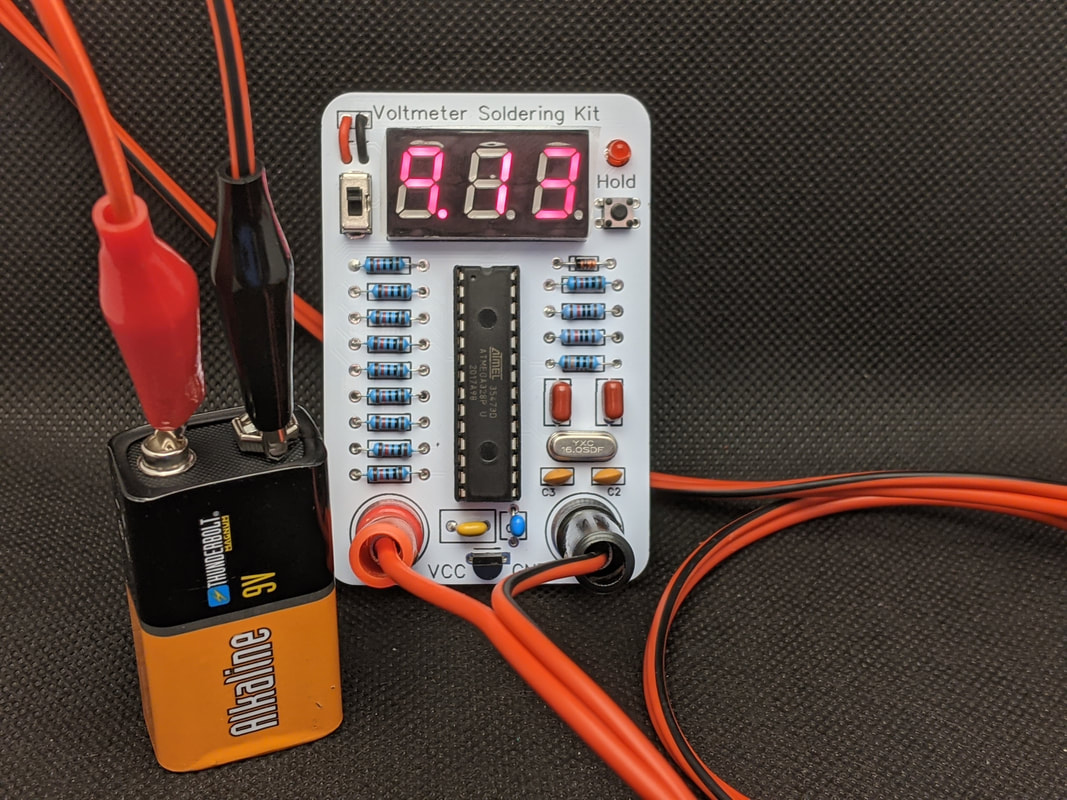
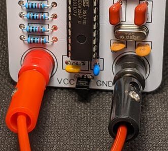
Turn on the voltmeter by flipping the switch to the on (upwards) position. Connect the banana plug leads by pressing them into the banana jack. Make sure that they are fully seated and the colors match (red lead to red jack, black lead to black jack).
To measure voltages, connect the red lead to the voltage source, and the black lead to the ground of the voltage source. If the wires are connected backwards, there will be no reading on the display.
To enable hold mode, press the button on the right of the voltmeter, and the indicator LED will light up. In hold mode, the screen will display the highest voltage reading since the button was pressed. The measurement will clear and the voltmeter will return to regular operation when the button is pressed again.
|
|
Calibrating the Voltmeter
If you test your voltmeter against a commercial one, you may find some slight discrepancies between the measured voltages. This is likely caused by slight variations in the resistors used for measuring the voltage (see the next section for more info on how the resistor divider works). If you want to try and get your voltmeter to be more accurate, you can calibrate it by tweaking some values in the code and re-flashing your 328P.
If you download the Arduino code for the voltmeter from the downloads page, you will see 4 calibration numbers towards the top. Here is what each oft them do, and how to modify them if needed:
vstep is used to convert the analog input of the 328P to a voltage value. If the voltage of things measure too low or too high, but not by a consistent amount, modifying this value can help.
offset is the value that non-zero measurements are offset by. This number rarely needs changing, since it is based on the 328P instead of the resistors.
The next two settings are not necessarily for calibration, but they are settings you can tune.
holdintensity determines how bright the hold LED is. A higher value makes the LED dimmer. The default value (3) makes it about as bright as the LED display.
LEDmode is the setting that tells the code what style 7-segment display you have. If the display is red, then it is most likely a common anode, in which case this should be set to 0. If the display green or blue, it is most likely a common cathode, in which case this should be set to 1.