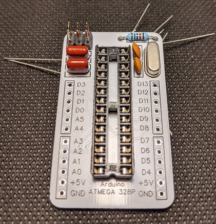
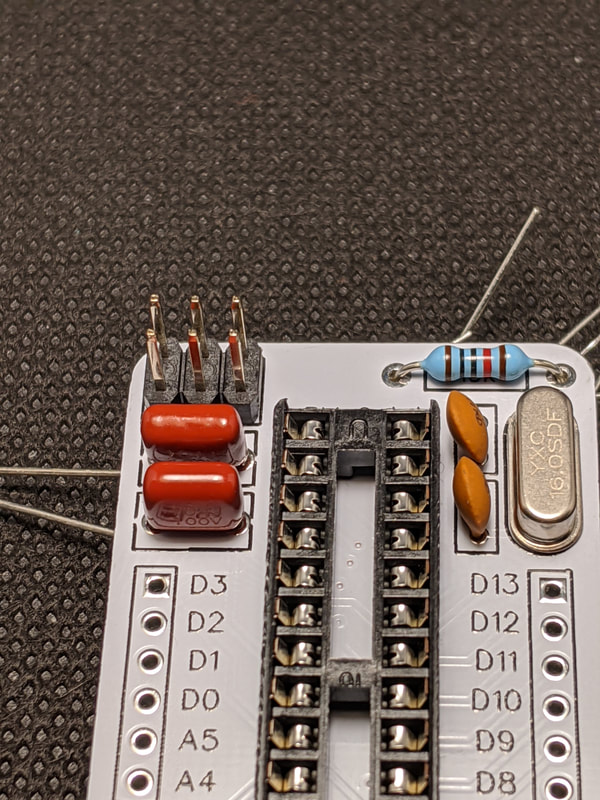
Step 1: Capacitors
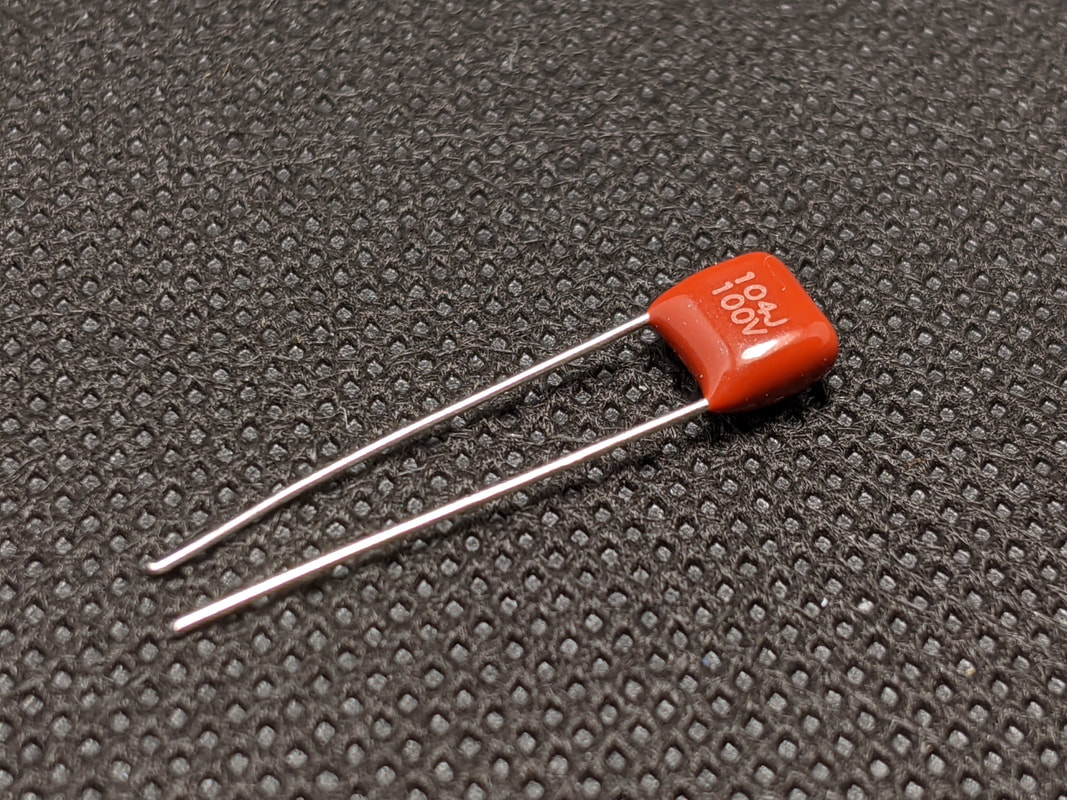
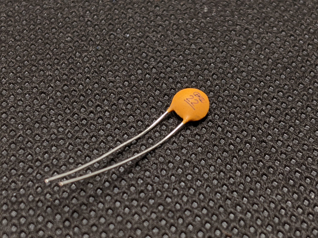
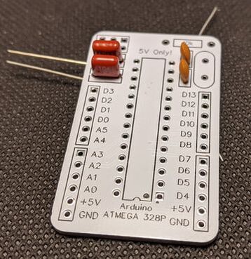
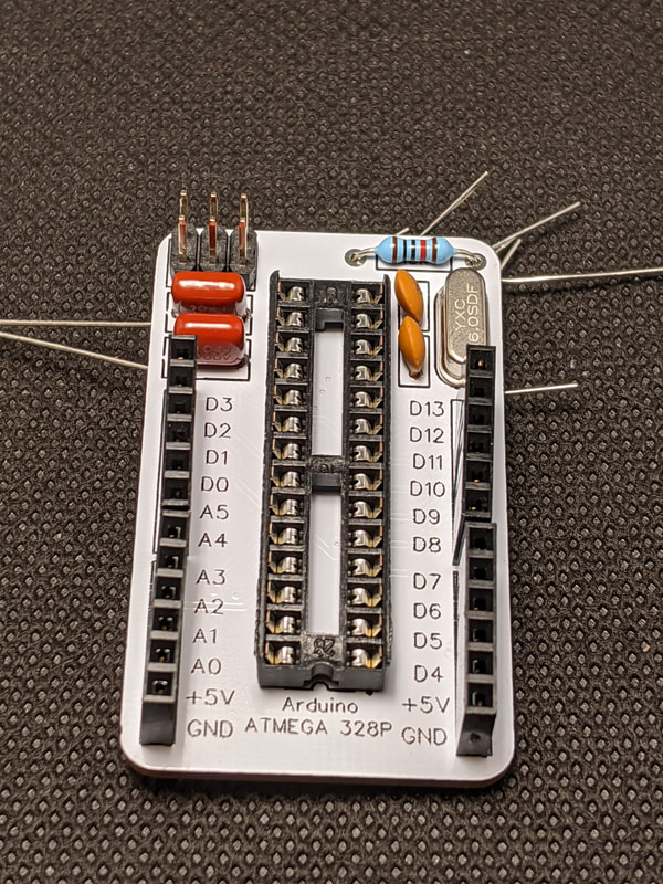
Solder the two 22pF (tan circles) crystal capacitors in the top right of the board, and two 100nF (burgundy rectangle) MCU capacitors on the top left of the board.
|
|
|
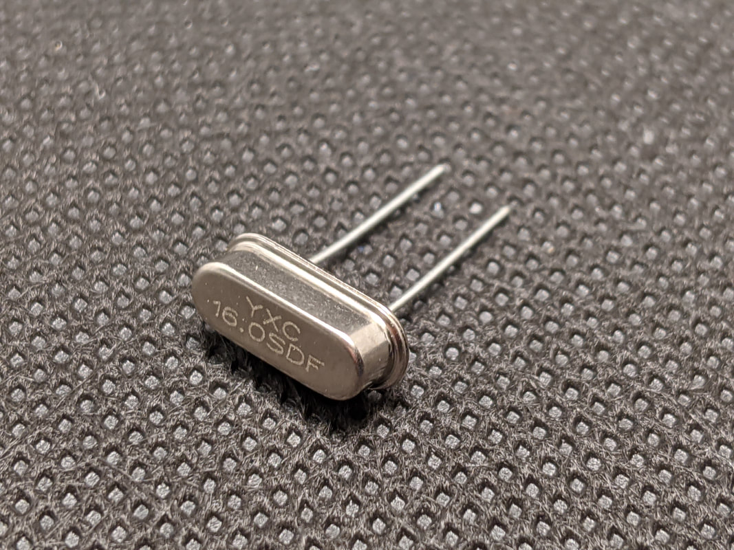
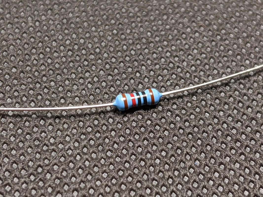
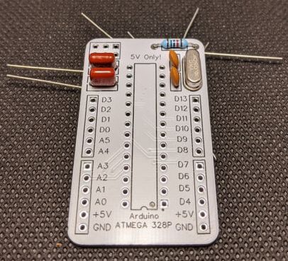
Step 2: Resonator + Resistor
Solder the resonator in the top right of the board, and a 10k resistor (red band from Bag 1) above that.
|
|
|
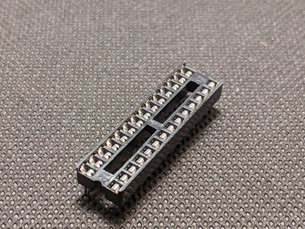
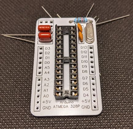
Step 3: DIP Socket
Solder the DIP socket in the center of the board. Make sure to match the notch of the socket with the notch on the silkscreen.
|
|
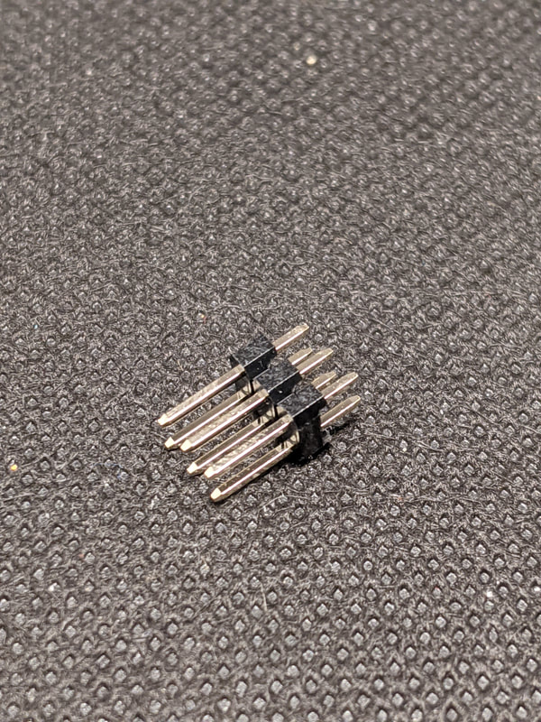
Step 4: ICSP Header
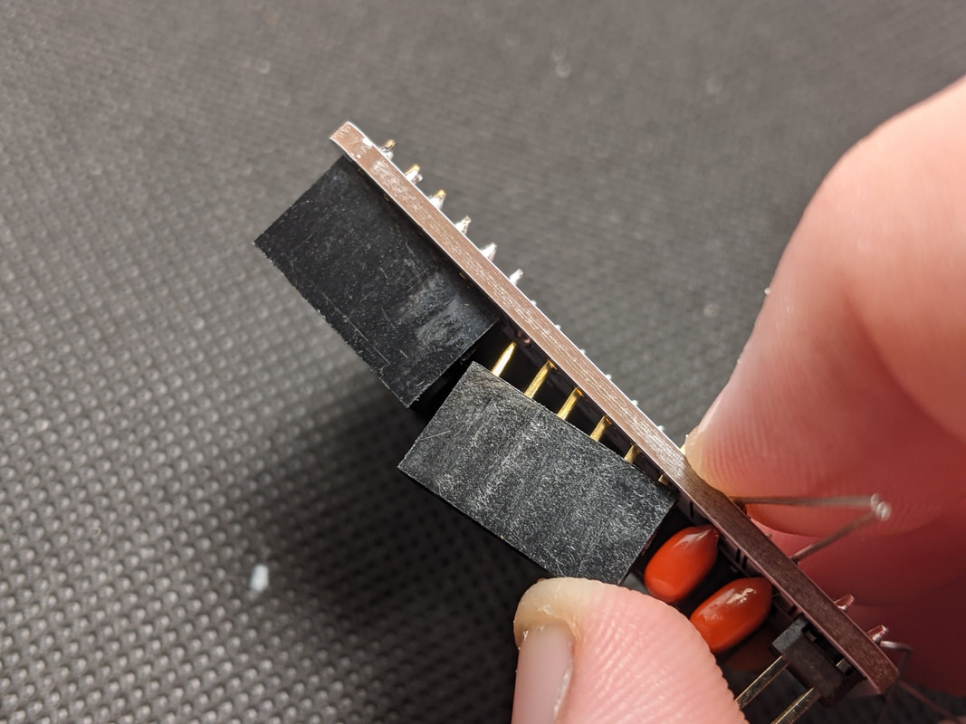
Solder the ICSP header in the top left of the board. The longer part of the pins should be coming out the top of the board.
|
|
|
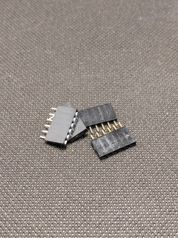
Step 5: I/O Headers
Solder the 4 10-pin I/O headers to the 4 header spots around the edges of the board. The long part of the header should be coming out the top of the board. To make sure they go in straight, I suggest filling one pin with solder, then pressing the header straight onto the board with one hand, as you melt the solder with the other. This one pin will now hold it in place as you solder the rest like normal.
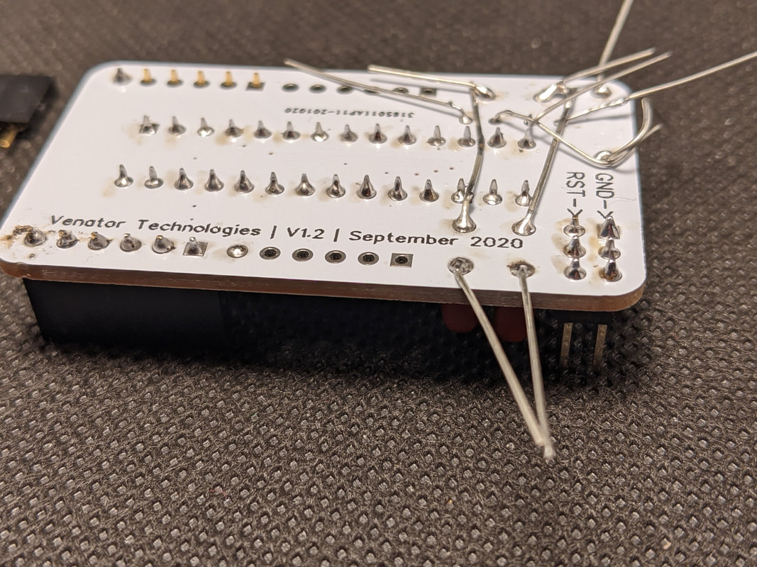
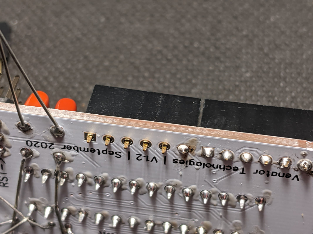
Once the headers are installed, you should clean up the leads on the back.
|
|
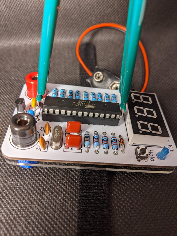
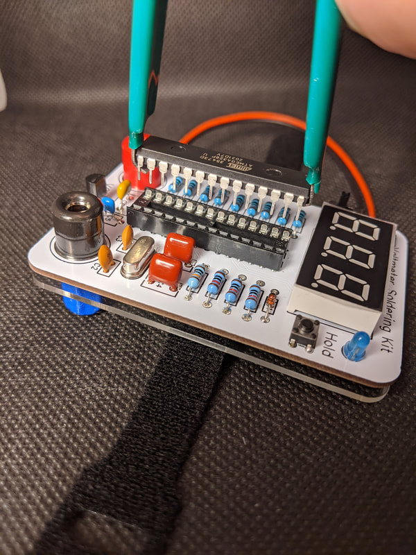
Step 6: Moving the Atmega 328P from the Voltmeter to the Breakout
To remove the Atmega 328P from the voltmeter and transfer to your breakout (or vice-versa), use the DIP puller tool included in the kit. Trying to do it by hand can damage or destroy the 328P.
First, hook the puller's fingers around the thin edges of the DIP. Grasp the DIP puller with one hand, and hold the board down with the other. While pinching the arms of the puller together, pull straight up on the puller. The DIP will suddenly break loose and come out. Make sure you pull up straight, or you may bend the pins on the MCU. If you pull slightly off to the side and some pins bend, just straighten them out by hand.
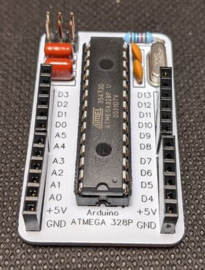
Install it into the breakout the same way you installed the MCU into the voltmeter. Make sure to line up the notch on the 328P with the notch in the slot!
|
|
|