Note on Opening Parts
|
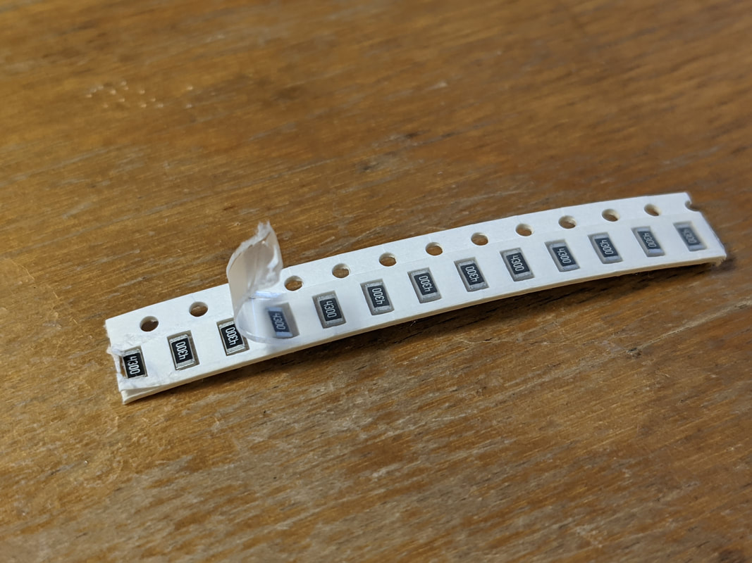
Many SMD parts come packaged on a tape, made of either paper or plastic with a thin, clear plastic top. When opening these tapes, use your tweezers to slowly peel back the clear plastic, while holding down the bottom of the tape. Be very careful with the paper tapes, sometimes you may grab a layer of the paper instead of the plastic, and you'll end up ripping the tape and throwing parts everywhere.
|
Step 1: 100 Ohm Resistors
|
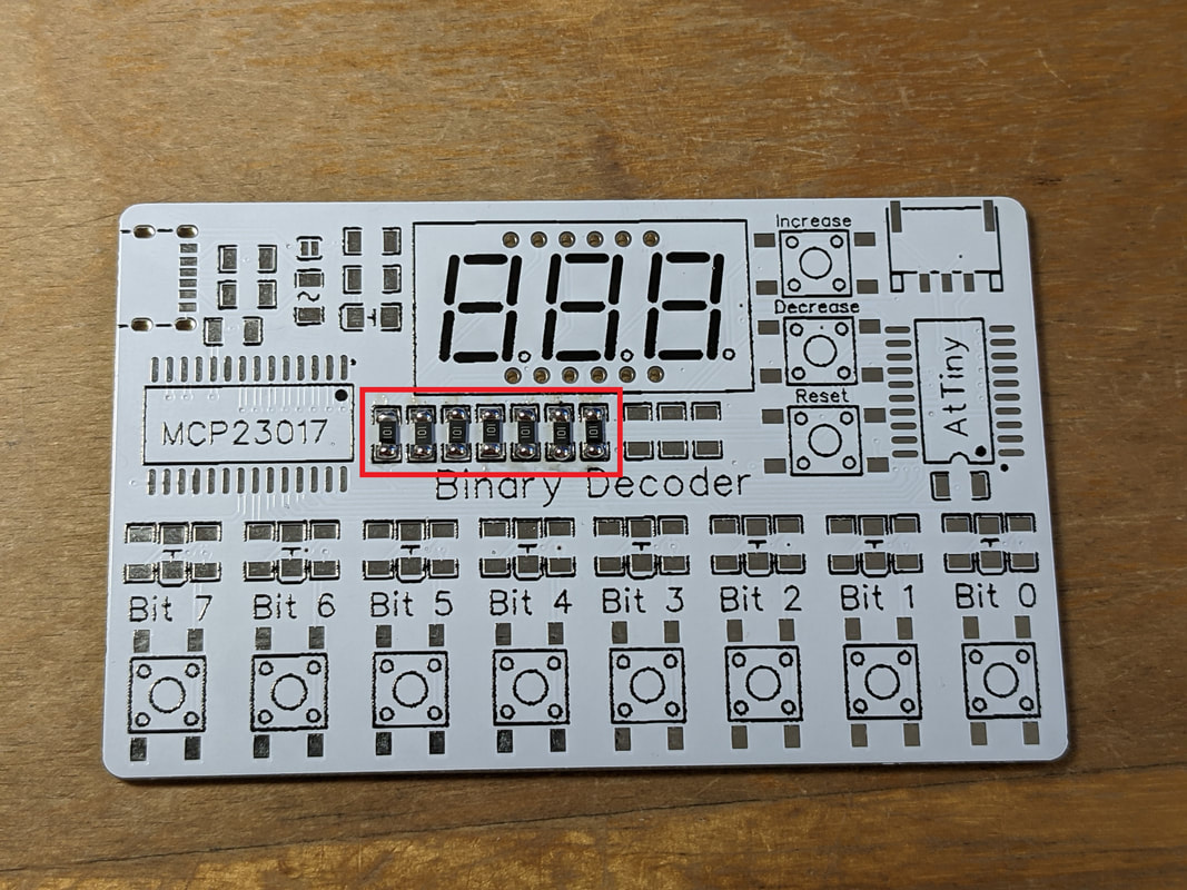
Install the 7 100 ohm resistors (labeled "101") (in some versions of the kit these may be 120 ohm, labeled "121") underneath the 7-segment displays. Remember that the orientation does not matter, but it will make the board look a lot cleaner if you orient all the parts facing the same way.
|
Step 2: 430 Ohm Resistors
|
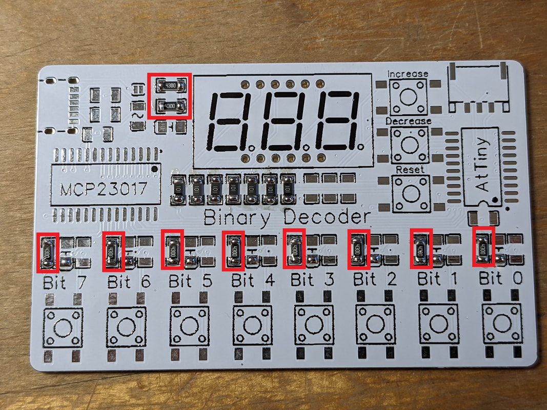
Install 10 430 ohm resistors (marked "4300"). 2 will go to the left of the 7-segment displays, and the remaining 8 will go above each of the 8 bit labels, on the left side of each group of 3 parts.
|
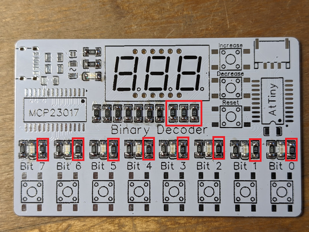
Step 3: LEDs
|
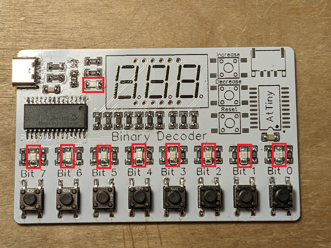
Solder 9 LEDs to the board. One will go below the 2 430 ohm resistors we did in the last step, and the remaining 8 will go to the right of the previous 430 resistors, above the button spots.
The cathode of the LEDs should be marked with a green dot. You should also double-check the LEDs with a multimeter to make sure that you are soldering them in the right orientation. The cathode of the bottom LEDs should go down towards the bottom of the board, signified by the rounded side of the silkscreen. The LED towards the top of the board should go towards the left of the board.
|
Step 4: 10k Resistors
|
Solder 11 10k resistors (labeled "103"). The first 3 go next to the 100 ohm resistors, and the remaining 8 go to the right of the LEDs from the previous step.
|
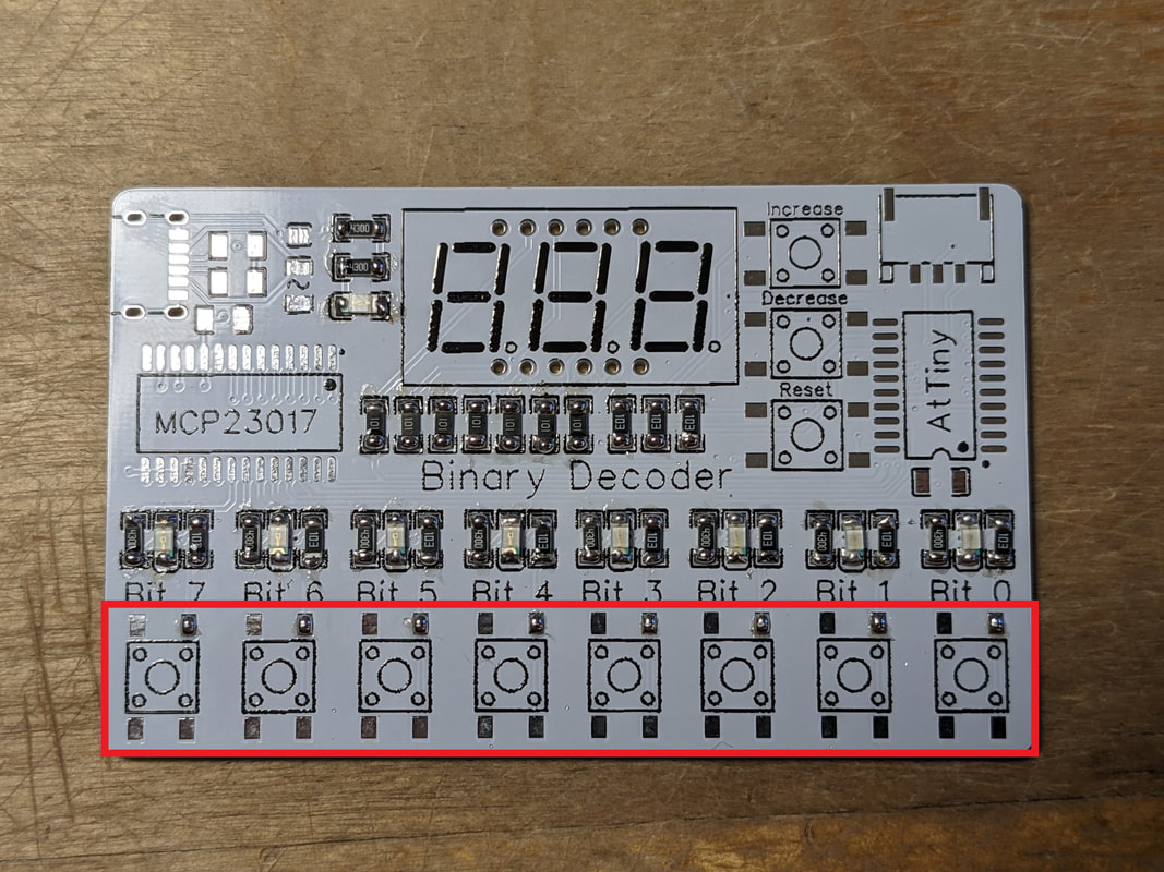
Step 5: Bit Buttons
|
Solder the 8 bit buttons along the bottom of the board. Put aside the remaining 3 buttons, we will get to those later. It is suggested that you start by soldering the pin in the top right, as they are connected to the least copper and will therefore be the easiest to move and align the button to get everything squared up.
|
Step 6: MCP23017 I/O Expander
|
|
Solder the MCP23017 in its spot on the left of the board. The MCP23017 ships in an orange plastic protective case, and is held in with friction. If you cannot get it out with your fingers, you can gently push a screwdriver or pen under the short side of the IC. The same process can be used to remove the AtTiny microcontroller from its protective case..
Make sure that each pin has a solid connection and there are no bridges between pins. If there are, use a solder plunger to remove them.
Tip: When soldering ICs and other components with lots of close-together pins, use significantly less solder than you think you need. You can more easily see if the solder makes a solid connection or not.
|
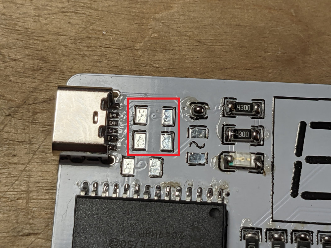
Step 7: USB-C Connector
|
|
The USB-C connector is the hardest part on this board to solder, so carefully follow the instructions and look at the pictures to the left. Start by putting some solder on one of the center pads, then place the connector on top of that, so that the legs align with their holes and it is sitting on top of the solid solder. Next, heat the solder and press down on the top of the USB-C connector, aligning the pins with their pads as you press. Then, add additional solder to make good, clean, filleted connections between the pads and the pins. If you form any solder bridges, remove them with a plunger or wick. It is ok if there is solder connecting the furthest left and/or furthest right pins to the metal shielding of the USB-C connector. Once complete, inspect the pins from multiple angles, you should be able to see the solder forming a clean joint, and the colored solder mask should be visible between the pins.
It is extremely important that you make sure there are no shorts between pins in the USB-C connector. Shorts here can not only damage your Binary Decoder, but also whatever device (computer, battery pack, wall wart, etc.) you plug the Binary Decoder into for power. To verify there are no shorts, use a multimeter in continuity mode to measure between the 2 sets of pads marked in the image to the left. If you read a short between the pink pads, then the center 2 pins are shorted together. If you read a short between the red pads, then there is a short between either of the 2 leftmost or rightmost pins. You should also check there is no short between either of the pink pins and either of the red pins, as this may indicate solder pooling under the connector.
If you have shorts and you are unable to fix them, that is ok. Just skip the following steps for the jumper, fuse, and 5.1k resistors. You will still be able to safely power the device through the programming port.
If everything checks out, you can solder together the jumper (2 small pads next to each other) to the left of the 430 ohm resistor.
Once you have confirmed all the connections are good, flip the board over and put solder into the 4 holes that the legs of the USB-C connector are in. The solder in these holes should be drawn down and form either a flat or a slight bowl. If the solder applied balls up above the surface of the board, you need to apply more heat (or apply solder from the other side).
|
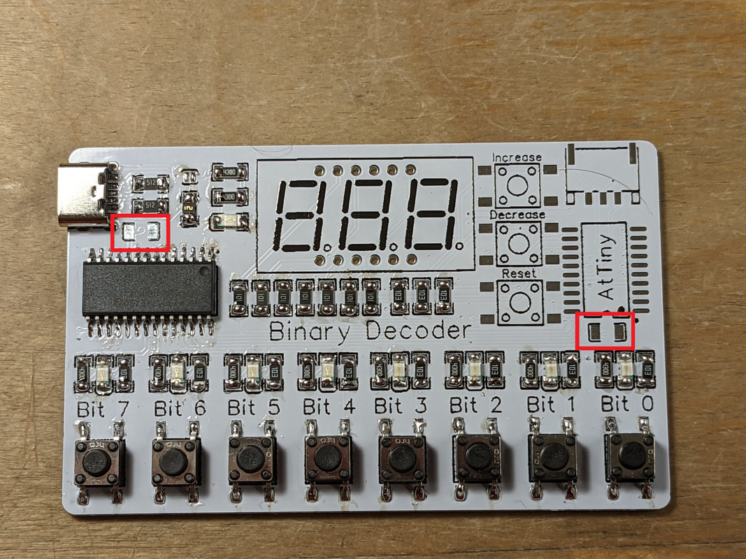
Step 8: 5.1k Resistors
|
Solder 2 5.1k resistors (labeled "512") next to the USB-C connector.
|
Step 9: Polyfuse
|
|
Solder the Polyfuse, also referred to as a self-resettable fuse, between the 430 ohm and 5.1k ohm resistors. Make sure that the solder fully covers the side and top of the fuse.
While soldering the top side of the polyfuse, you may accidentally get too close and unsolder the jumper above it (like in the second image to the left). If this happens, make sure to re-solder it before continuing.
|
Step 10: 100nF Capacitors
|
Solder 2 100nF capacitors, one below the 5.1k ohm resistors and one above the LED for Bit 0. The polarity of these capacitors do not matter. Since the capacitors connect between 2 planes, they may take extra time to solder.
|
Step 11: AtTiny Microcontroller
|
|
Remove the AtTiny microcontroller from its plastic case and solder it to the right of the board. Make sure to align the dimple on the top of the board with the mark on the solder mask. Closely inspect for bridged pins and fix it with a solder plunger.
|
Step 12: Control Buttons
|
|
Solder the 3 buttons to the left of the AtTiny. It is suggested to start with the pad in the top left corner, as it is connected to the least copper. When soldering, be careful not to bridge the pins between the AtTiny and the buttons. If you do, remove the bridge with a solder plunger.
|
Step 13: Programming Port
|
|
Solder the programming port in the top right of the board. The pins on this part are in a fairly awkward orientation, so you will have to use the wick technique discussed in the "How to SMD Solder" section. Once the 3 back pins are soldered, do not forget the 2 stress relief ones at the front. When done, remove any excess solder from the pins.
|
Step 14: 7-Segment Display
|
|
Align the 7-segment display so that the decimal points are towards the bottom, and push it through the holes in the board. Sometimes the pins on the bottom of the 7-segment display get bent during shipping, and you will have to bend them back to go through the holes.
Once through the holes, solder one of the pins, and flip the board over to make sure the display is oriented properly and squared up. Adjust as needed, then continue to solder the rest of the pins. Depending on what LED colors your kit includes, there may be more holes than pins, this is ok. You can ignore the holes that do not have pins in them.
Once complete, safely remove the excess leads from the back of the board with flush cutters while wearing safety glasses.
|
Step 15: (Optional) Cleaning
|
|
Soldering will leave behind a lot of debris, you'll notice a liquid-like substance on the board as well as many spots that are brown and caramelized. The majority of this is flux, but there are other contaminants that cover the board as well. To make your project look better, you can clean this debris off.
Consult the datasheet for your solder and rosin for product-specific cleaning tips, but my general go-to strategy is to douse the board in 91% Isopropyl Alcohol, and then use an electric toothbrush to scrub the board until there is no visible debris left. Set the board aside and let it dry before use. It should be obvious, but for liability reasons I do have to state that you should not use this toothbrush for anything else besides cleaning PCBs.
If you are planning to clean the board, avoid removing the protective film on the 7-segment displays until after cleaning. The ink on the top of some 7-segment displays can be degraded by some cleaning agents. If you already removed the protective film and want to clean the board, avoid getting any cleaning agent on the black top of the display.
|
Step 16: Final Checks
|
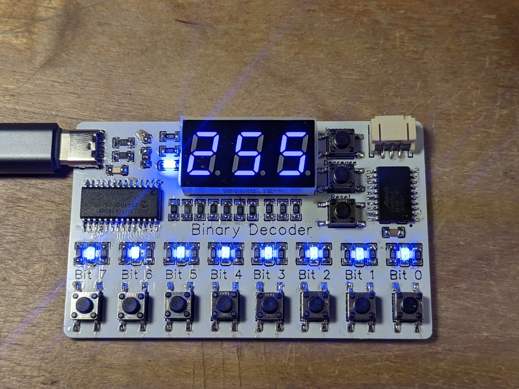
Your Binary Decoder should now be complete! Do some final visual inspections for damage or missing solder joints, and do a final continuity check between VCC and GND, easiest accessible on either side of the capacitors. If there is no continuity from one side of the capacitor to the other, you are all set to plug it in. If the lights do not start coming on immediately, unplug it and go to the Troubleshooting section. Otherwise, you are all set!
|