Step 1: Same as Binary Decoder...
|
There are a handful of parts on this board that are soldered the same as on the Binary Decoder, so let's take care of those first.
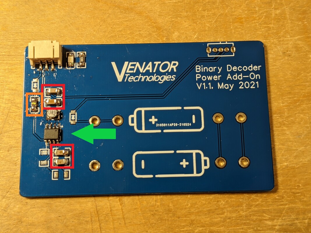
Start with the 430 ohm resistor and LED at the top of the board. The anode of the LED goes towards the top edge of the board. Next, solder the programming port next to the LED in the top left. Once that is done, solder the fuse (orange spot to the left) and the 8 pin IC (green arrow), being sure to align the dimple with the silkscreen mark in the top right corner. Then, solder the 4 22uF capacitors in the spots marked in red. These connect right to copper pours, so they may take more time than normal to solder.
|
Step 2: Inductor
|
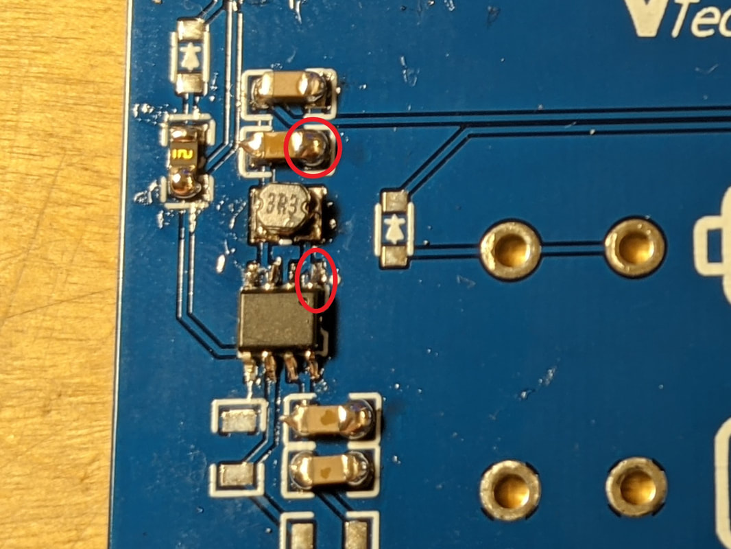
The inductor is the hardest part of this board to solder. There is a whole section on tips to solder the Inductor in the previous section, "How to SMD Solder." Once you feel the inductor is properly soldered, you can verify it with the continuity mode on a multimeter. Measure continuity between the right side of the top capacitor and pin #1 of the IC. If soldered correctly, it should read as a short.
|
Step 3: Diodes
|
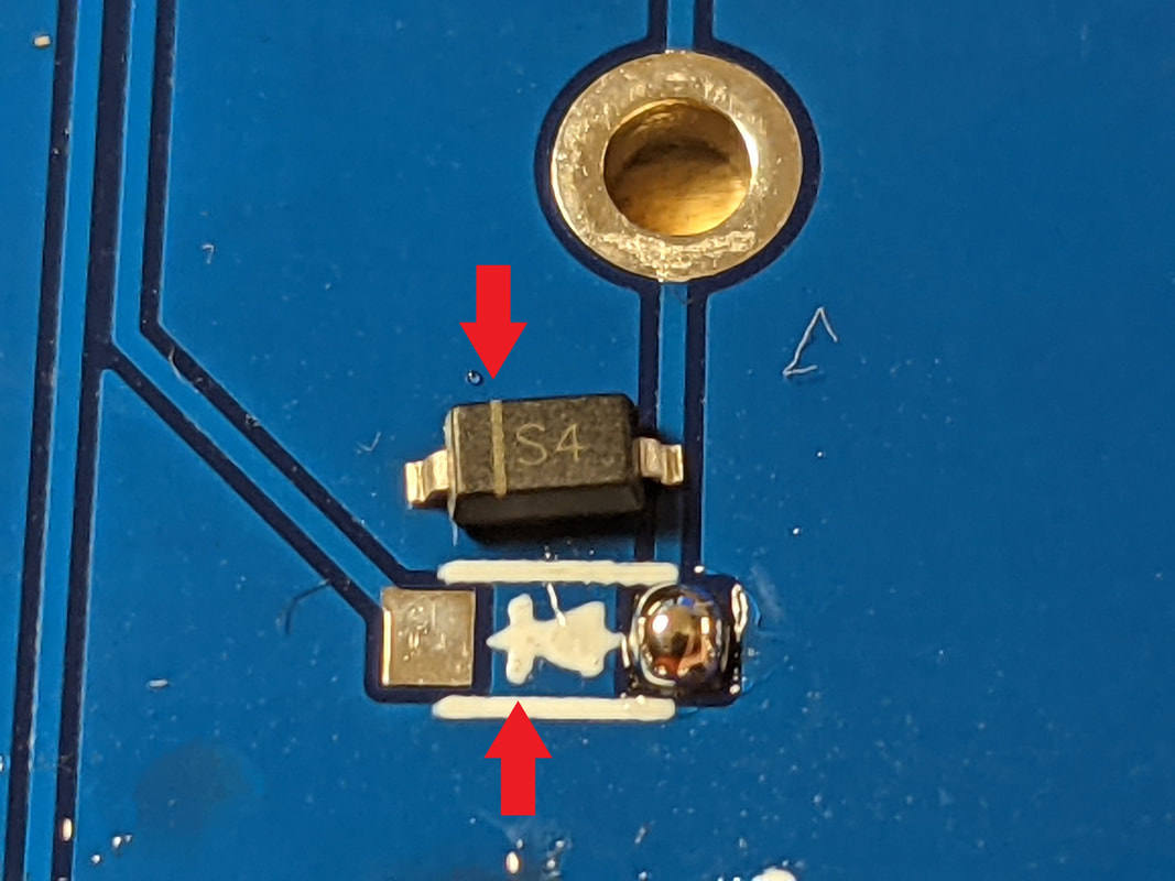
Solder 2 diodes to the Power Board; one to the right of the inductor, and one above the fuse. The diodes will have a line marking their orientation, that should be aligned with the line on the silkscreen, as shown to the left.
|
Step 4: Resistors
|
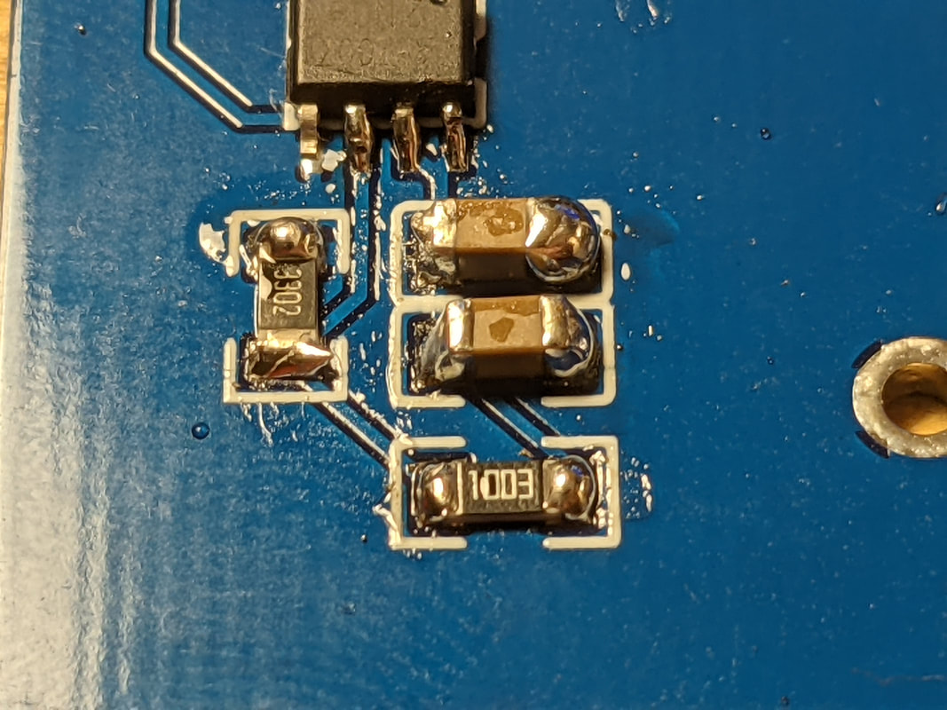
There are 2 critical resistors at the bottom left of the Power Board, a 33k ohm (labeled 3302) and a 100k ohm (labeled 1003). The 100k ohm resistor should go below the capacitors, and the 33k ohm resistor should go to the left of the capacitors.
|
Step 5: Switch
|
|
Put the switch through its holes in the top right corner, and solder it from the underside. If you want, you can also rotate the switch 180 degrees so that the arm is over the board instead of on top. Alternatively, you can not install the switch and instead bridge solder between the 3 center holes for the switch, to always have the Power Board on whenever batteries are installed.
When soldering the switch, be careful of the 2 larger outside holes. These connect directly to the metal housing of the switch, so it will heat up fast when soldering there. Avoid touching the switch while soldering these pins.
|
Step 6: Battery Clips
|
|
Install 4 battery clips in their spots on the center of the board, with the openings facing each other. The clips are spring-loaded, and should take a bit of force to push through the board. Once in place, the clip's bottom will be flush with the board and the clip will be retained by the spring force.
If your board is marked V1.1 in the top right corner, you will need to apply electrical tape or some other form of insulation between the 2 left battery clips, to prevent shorting. It is ok if the right clips are touching.
If your board is marked V1.2 in the top right corner, you do not need to worry about the insulation between the left clips. However, be careful not to bend them together (especially when installing batteries) as this can lead to a short. It is preferable to put some electrical tape or similar insulation on the side of the battery clip like in V1.1, just to be safe.
|
Step 7: (Optional) Cleaning

|
(Text coming soon)
|
Step 8: Testing
|
|
Flip the switch to the rightmost position, and put batteries into the clips. Make sure that the polarity of the batteries line up with the + and - marks on the silkscreen. Verify that the metal clips on the left side are not touching each other. If so, immediately remove the batteries.
Flip the switch to the leftmost position, and immediately the light at the top of the board should come on. If it does not, shut off the board immediately and continue to the Troubleshooting section.
If the light comes on, measure the voltage between the center and leftmost pin on the Power Board's programming header. It should be between 4.6 and 5.1 volts. If it is significantly higher or lower, verify that the batteries are fresh and that the voltage divider resistors are oriented properly.
|
Step 9: Installation
|
|
It is imperative that you do not both power the Binary Decoder from the USB-C port and the Power Board. The USB-C port also can not be used as a power source (i.e. for charging your phone or powering other projects). If you are planning to exclusively use the Power Board, it is strongly recommended that you disconnect the USB-C port. This can be done by desoldering the jumper and fuse to the right of the USB-C port.
Flip over the Binary Decoder and place the 4 board spacers in the corners. Put a dot of glue connecting the flat side of each board to the PCB. Hot glue is recommended for this, as it can be removed if needed. Once the glue solidifies, put a dot of glue on the top flat surface of each board spacer, and the place the Power Board on the glue, pressing down on the Power Board to get a good glue connection.
Connect the included JST cable between the Binary Decoder and the Power Board. You can now power on the Power Board and the Binary Decoder will come on as well.
You can leave the cable in the air above the boards, or you can tuck it between the boards and secure it with a dot of hot glue.
|