Incomplete Solder Joint
|
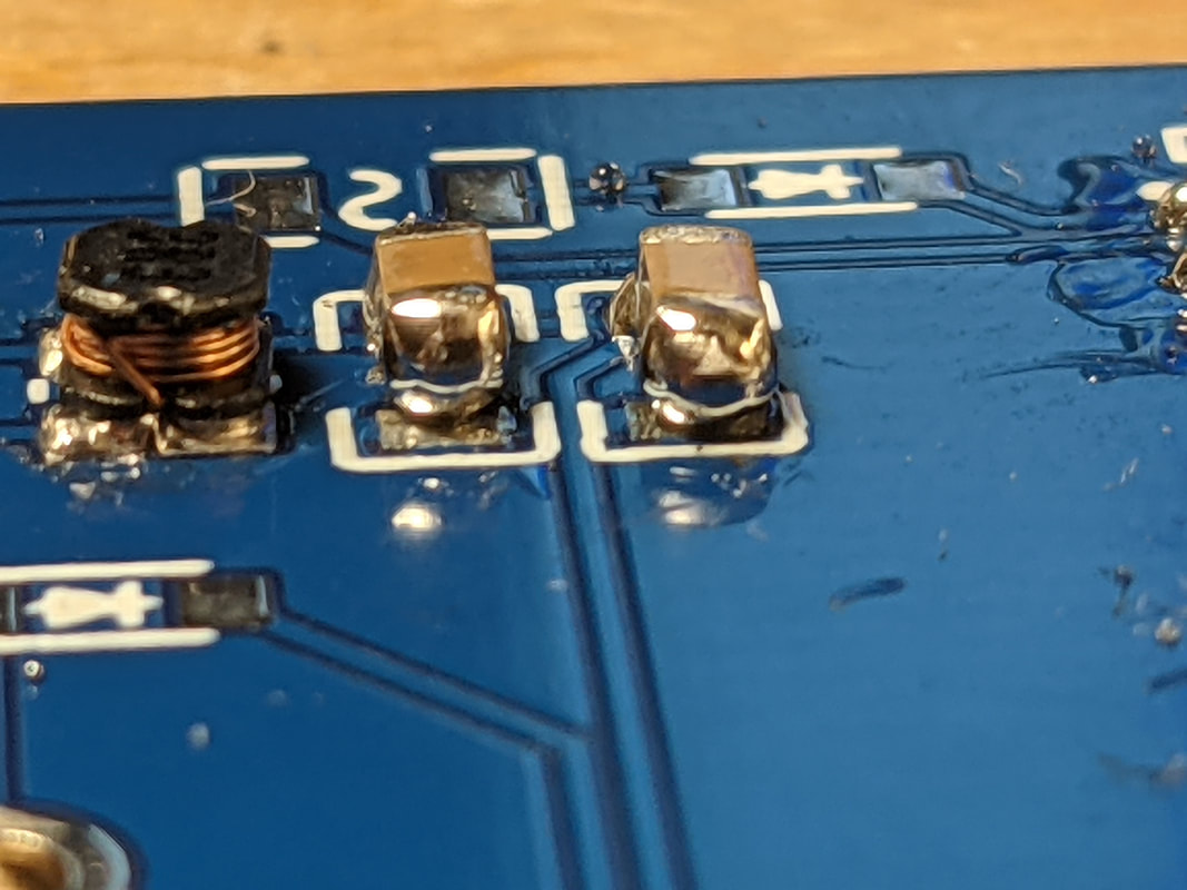
Incomplete solder joints are the most common issue when SMD soldering. Parts that connect to pours, like capacitors, are especially vulnerable to this. Sometimes, the solder will be hot enough to stick to the side of the part but not to the pad underneath. In the picture to the left, the capacitor on the left is not actually soldered to the board (you can see the solder is covering the end of the capacitor but not filleted to the board). You can find these joints with visual inspection, but also having less solder on the joint will make it more obvious. If you use a solder plunger to remove the bulk of the solder on a joint, what is left should form a small radius between the part and the pad (covering the full shape of the pad).
If you notice that one LED or one button is not working, it is likely that there is a bad solder joint somewhere on that circuit path. Go through and "reflow" (put your iron on the solder so it melts and re-forms the connection) each connection along that path to see if it changes anything. For instance, if an LED along the bottom was not lighting up, I'd start by reflowing all the pins on the MCP23017, then the resistors around the LED, then the LED itself.
|
Bridged Pins
|
|
Any multi-pin parts are susceptible to bridging between pins. This can cause minor issues, like a light coming on when it is not supposed to, to major issues, like a short-circuit destroying part of the circuit.
Bridges are not always large, obvious connections like in the pictures to the left. Sometimes, there is a small amount of solder hidden behind the pins. I like to reflow each pin after soldering an IC, to help alleviate any of these tiny bridges. When the solder is liquified, surface tension pulls any small bridges back to the pads and pins.
|
Power Board Humming/Buzzing/Whining

|
The Power Board boosts voltage by quickly charging and discharging the inductor. Under a heavy load or with a lot input voltage, sometimes the boost converter will start operating at a frequency that the human ear can hear. This will result in a very faint humming or whining, commonly referred to as "coil whine." The boost converter is fine to operate like this, but it can get annoying if you are in a quiet room, so here are some tips to eliminate it if needed;
1. Use fresh alkaline batteries. The boost converter will have to work less if the input voltage is closer to the target voltage, so use fresh AA batteries. Make sure to use alkaline as opposed to NiMH, as the latter has a much lower voltage.
2. Cover the inductor. The most probably part to be whining is the inductor. Usually, the inductor itself is not large enough to act as an effective speaker, but rather it is making the PCB around it resonate and that is what is producing the audible sound. Sometimes, simply reflowing the solder on the inductor or coating the inductor in hot glue will stabilize it enough to remove the whine.
2. Remove the battery diode. Warning: doing this does increase the risk of damaging your Power Board if batteries are put in incorrectly, do at your own risk. Diodes drop a certain amount of voltage, so a nominal 3 volts from our batteries may only end up as 2.8 when it gets to the boost converter. You can remove the diode that is in front of the batteries (the one to the right of the inductor), and short the 2 pads together with a length of wire or solder.
|