If you are new to electronics, I'd suggest reading this first. This section will go through identifying some of the common electrical components you will see in your DIY projects, including in this kit.
Common Electrical Components
Here are some of the electrical components we use in this kit. Don’t worry if you do not fully understand yet, later on we will go over how these parts are used in the circuit.
|
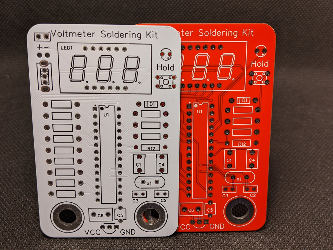
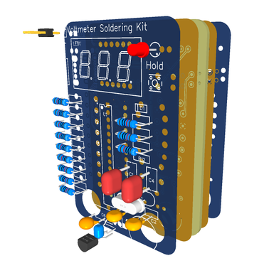
Printed Circuit Board (PCB)
A PCB (Printed Circuit Board), sometimes shortened to “board” is the heart of any electronics project. It is the flat piece that everything is soldered to. A PCB is usually a nonconductive material, like fiberglass, that is then covered in copper to form “traces” that connect multiple points on a board. Think of the PCB like a bunch of wires, smushed together into a small and convenient form factor. |
|
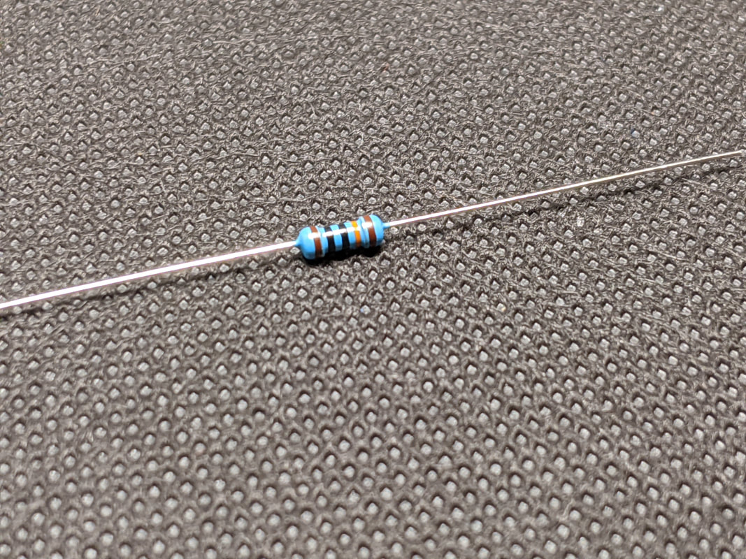
Resistor
A resistor is one of the most common electrical components. As the name implies, it creates resistance in a circuit. This can be useful for setting the amount of current or voltage going through a wire. Nearly every electrical system ever created uses resistors in one way or another. In this kit and for most DIY electronics work, resistors can be identified as a beige or blue cylinder with colorful bands on it, with a metal lead coming out of either end. The colored bands can be decoded and used to determine the resistance level of the resistor. Resistors do not have a polarity, so it does not matter which lead goes into which spot on the board. |
|
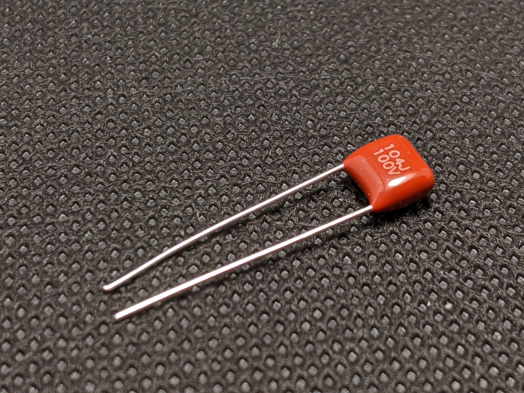
Capacitor
After the resistor, the capacitor is the second most common electrical component. It is used to momentarily store a small amount of electrical charge, like a small battery. In our circuit, we use capacitors to help compensate for sudden spikes in power usage, such as if we turn on a bunch of LEDs at once. Capacitors come in many shapes and sizes, depending on their intended use. The capacitors in this kit do not have polarity, so they can be connected in any orientation. Be careful, though, some capacitors do have polarity and may explode if connected incorrectly. |
|
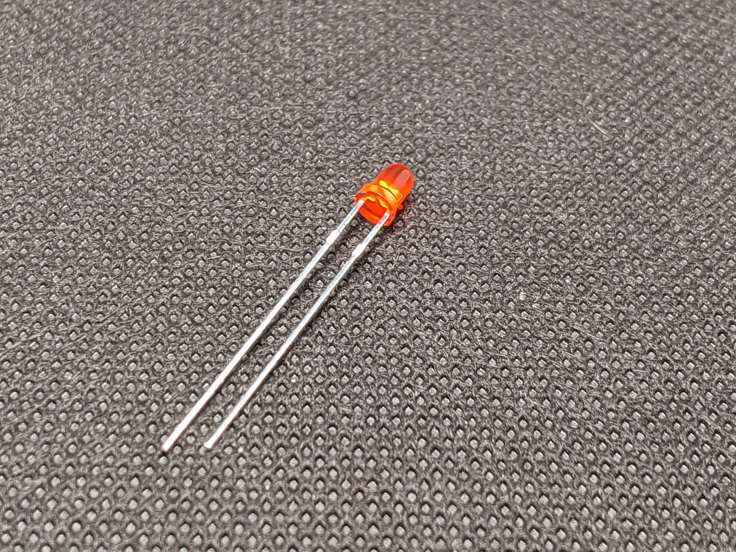
LED (Light Emitting Diode)
An LED, or Light Emitting Diode, is like a small lightbulb for our project. When we flow electricity through it, it will light up. LEDs will try and use as much power as you supply to them, so they usually will have a resistor connected before or after to reduce the amount of current flowing through. LEDs do have polarity. The positive side of the LED, called the anode, is usually the one with a longer lead. The negative side, the cathode, is the shorter leg. Some LEDs are also flat on the side that corresponds to the cathode pin. Don’t worry if you connect the LED backwards, it will not break anything. The LED will just not light up. The numerical display for this project is also made up of LEDs, arranged in a pattern to show numbers when we turn certain LEDs on or off. |
|
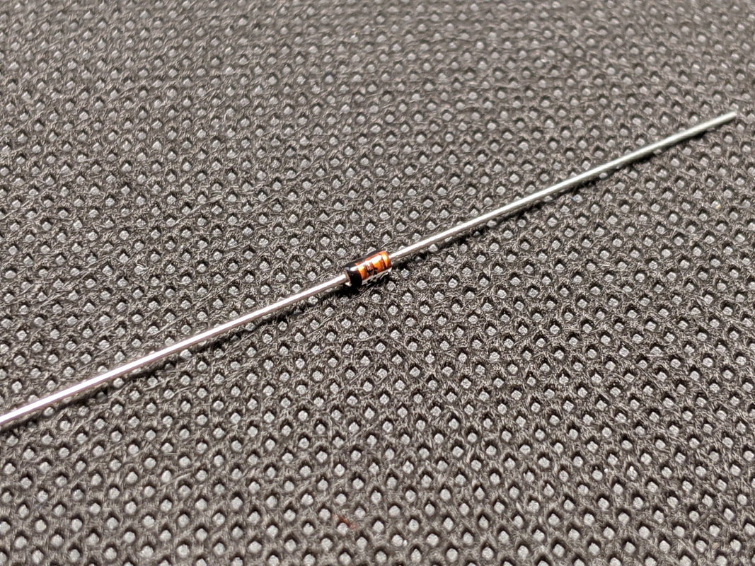
Diode
A diode is an electrical component that only allows electricity to flow through it one way, and blocks it in the other direction. We use a diode in our project to protect against connecting the battery incorrectly, and diodes inside of the 328P protect our microcontroller if you were to connect your voltmeter the wrong way to something. The downside to diodes is that they get hot and waste some electricity when they are in use. The diode in our project will convert about 1 volt to heat. However, it is worth it to protect the rest of the circuit from getting fried if we connect something backwards. |
|
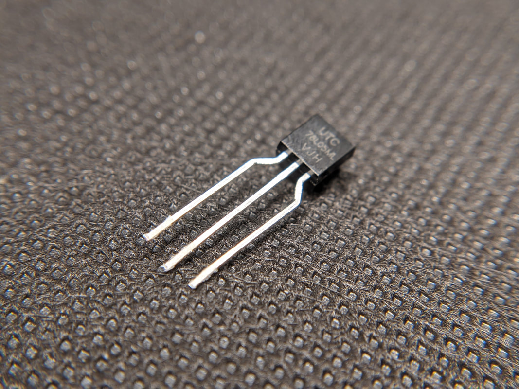
Voltage Regulator
Our project needs a specific voltage to work, and we may not always have the right battery to supply that. So, we can use a voltage regulator to bring the voltage to the right level. The voltage regulator in this project is a linear low dropout regulator, meaning that it can take a higher voltage and convert it to a lower voltage, turning the rest to heat. Our project can take an input of up to 30 volts and will always output 5 volts to the rest of the system. There are other types of voltage regulators that can convert a high voltage to a low voltage without as much heat, but they are more complex to build. There are also voltage regulators that can take a low voltage and convert it to a high voltage, like if you need a 3 volt coin cell battery to power a 5 volt Arduino. |
|
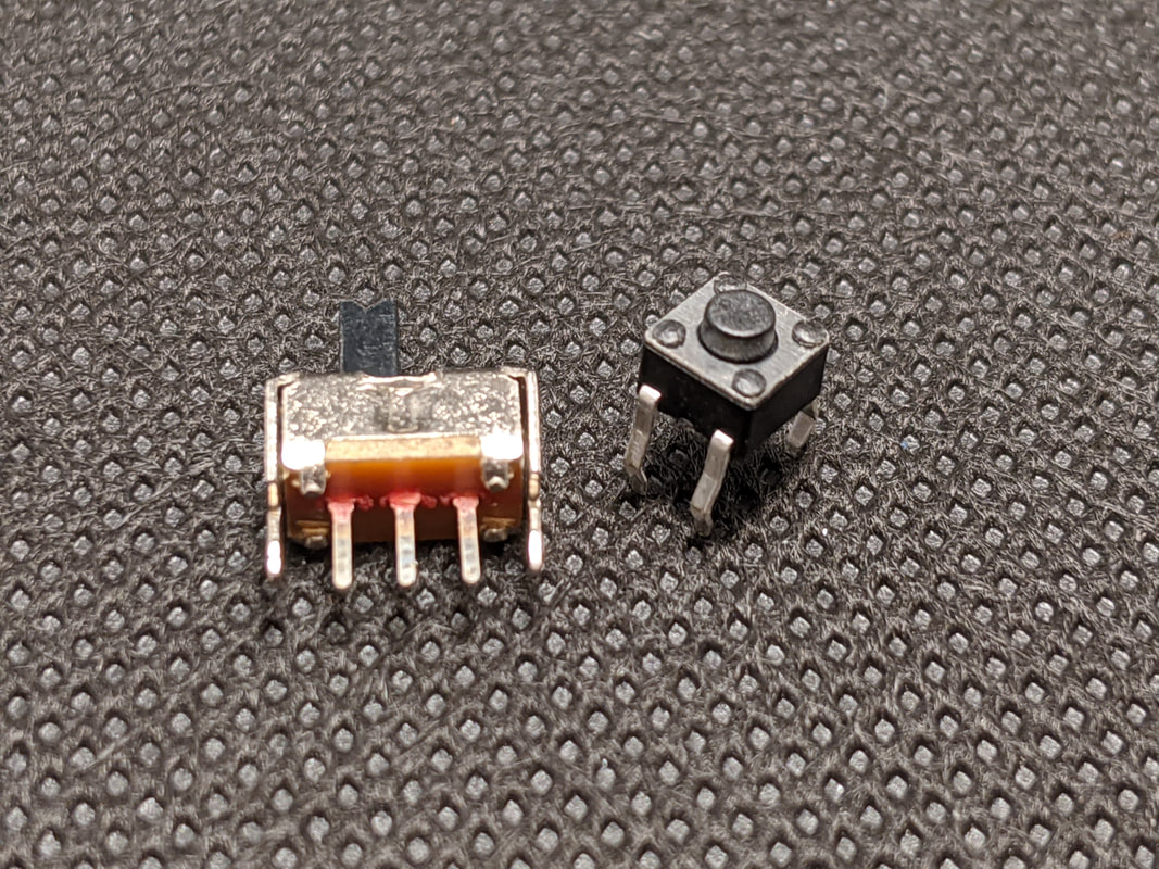
Momentary Switch
A momentary switch is the electronics term for a button. It is called a momentary switch since it only turns on for the moment you are pressing it, then immediately returns to its original state when released. We use a momentary switch in this project to enable the hold functionality. When we press the button, it sends a high signal to the microcontroller, telling it to turn on the hold. Then, if the microcontroller detects another high signal from the button, it knows to turn it off. Toggle Switch
A toggle switch is used to set something on or off, or switch between two different electrical paths. A common example of a toggle switch is the light switches in your house. We use a toggle switch in this project to connect or disconnect the power input from the rest of the circuit. If it was not there, we’d have to remove the battery any time we were not using the voltmeter. |
|
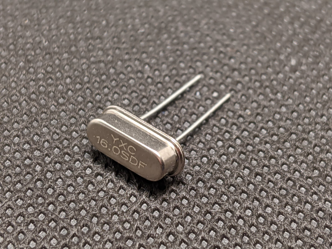
Crystal Resonator
A crystal resonator is a special component that helps our project keep track of time. When a voltage is applied to some crystal materials, they will vibrate at a specific frequency, usually thousands or millions of times per second. We can then use that specific frequency to count time. If you ever see a clock that says “Quartz” on the front, it has a quartz crystal inside that is helping it keep track of the seconds as they go by. The resonator allows our microcontroller to perform accurately timed functions. |
|
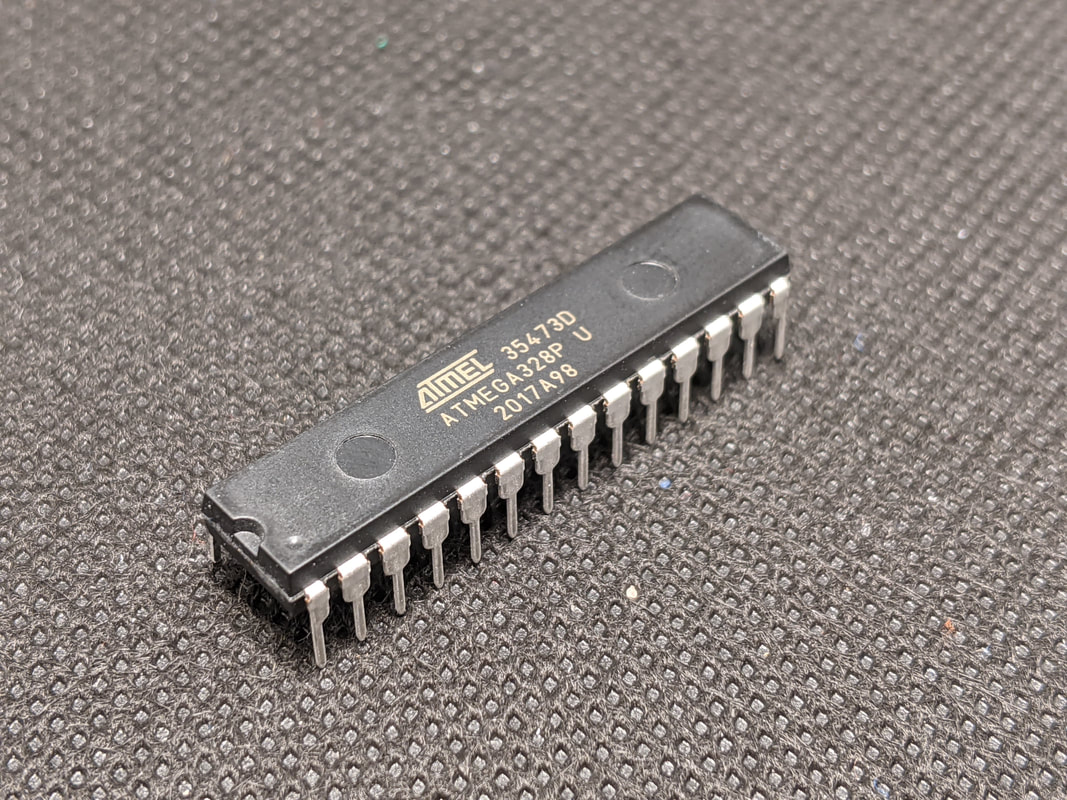
Microcontroller (MCU)
The microcontroller is what makes many complex projects operate, it is basically a small and simple computer. It can be programmed with software to perform certain electrical operations when we want it to. This can be as simple as turning on and off an LED once a second, to as complex as reading multiple sensor inputs and using that data to control a model rocket or airplane. |
Common Electrical Packages
A package is a standard form factor that electrical components come in, to make it easier to integrate and identify them. While every component has a package name, below are just a few that you will hear mentioned in these instructions.
|
|
Axial
Axial packages mean that there is a lead extending straight out from either side of the component. These leads usually need to be bent over to go into the PCB. The most common example of an axial package is a resistor. |
|
|
DIP (Dual In-line Pin)
DIP (Dual In-line Pin) packages are for complex electrical parts like integrated circuits (ICs) and microcontrollers. They always have two sets of pins coming out of either side of a rectangle. They can be directly soldered to a PCB, but it is better practice to solder a socket to the board then plug the DIP into it, so that you can replace or remove it later. You can tell which way a DIP package should be oriented based on the positioning of a groove or large dot on the top of the package, which is the “top” of the package. There will be a corresponding mark on the silkscreen or socket. |
|
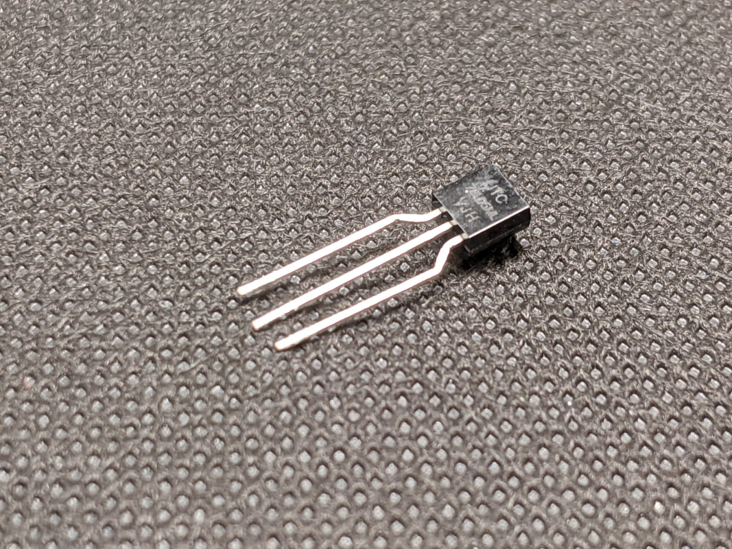
TO-92
The TO-92 is a package with 3 pins and a semi-circle plastic housing. It is mostly used for transistors, but other 3-pin components like temperature sensors and small voltage regulators also often use the TO-92. The semicircle of the package must be lined up with the semicircle that is printed on the board to orient the component correctly. |
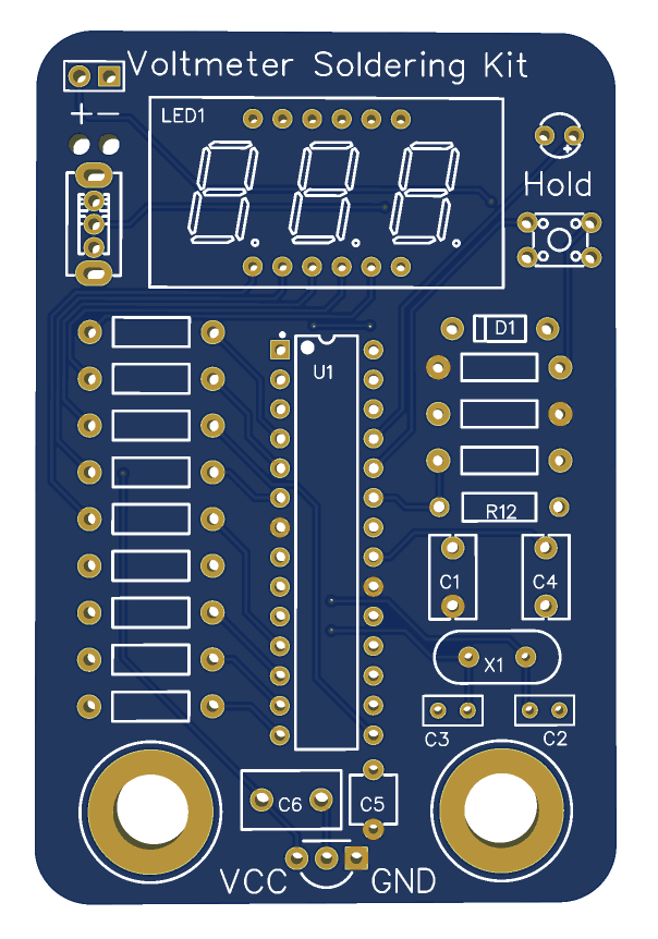
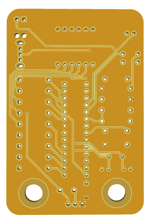
Anatomy of a PCB
|
Since nearly every electronics project uses a PCB, let’s talk more about what it is and how it works. As mentioned before, A PCB, or Printed Circuit Board, takes the place of a bunch of wires in an electrical system, helping to secure and connect different electrical components. The PCB has a core of fiberglass, that copper and other materials are then printed on top of (hence the name). Most PCBs only have copper on the top and bottom, but some more complex boards can have multiple layers of copper sandwiched between multiple layers of fiberglass. Electrical signals get from one level of copper to the other through small holes called “vias” that connect the layers of copper with metal. You can see some of these vias if you look closely at the PCB for this project. One advantage of the through-hole parts we are using in this project is that they act as a via, connecting to both the top and bottom layer.
The copper on the PCB is deposited to form connections between points, called traces. If you hold the PCB at an extreme angle in light, you can see the slightly raised areas of copper and the valleys of no copper between them. For PCBs that need to handle a lot of power, like a battery charging circuit, these traces may be wider or thicker to allow for more current to flow. Since traces are all in 2 dimensions, they cannot cross. This is where the multiple layers of copper come into play. If a trace needs to cross another, we can use a via to send it to the other layer, then use a via to bring it back up once it is passed. Each layer of the PCB has a name, let’s look at what each layer looks like and does. |
|
Top Silk Screen
The top silkscreen is the writing and images on the top of the board. The silkscreen is commonly used to show the orientation, name, and position of components. Top Solder Mask The solder mask is the main color of the PCB. In addition to adding the color to the board, the solder mask provides a nonconductive barrier that solder will not stick to. |
|
Top Paste Mask
The paste mask is the exposed metal parts of the PCB that components can be soldered to. A small amount of solder is applied to these spots to make a nice and level surface that easier to solder to. Top Copper Layer The copper layer is the layer where all the connections are made on the PCB. The copper is what forms the traces and connects parts. In addition to traces, the copper layers contain something called a "copper pour." For connections that most parts need (such as ground), rather than running individual traces, the entirety of the unused board space is filled with copper that connects all these pins together. |
|
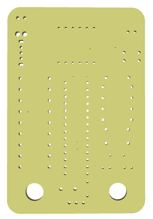
Substrate
The substrate separates the copper layers of a board. It makes up the majority of the thickness of a PCB, and gives it most of its structural integrity. |
Since this is a 2-sided PCB, it has a copper layer, paste layer, solder mask, and silkscreen on the bottom that each serve the same purpose as the top ones do.