If this is your first-time soldering, let us go over some of the basics of how to solder before we assemble the kit. The best way to learn to solder is by watching. I would suggest watching videos online about the basics of soldering in addition to these instructions, to best prepare yourself.
How Soldering Works
Soldering is the process of joining two or more metal objects by melting and applying some intermediate metal material referred to as solder. It is often used in electronics as it offers a way to connect electrical components with a strong, yet reversible, conductive bond.
Soldering Equipment Names and Usages
|
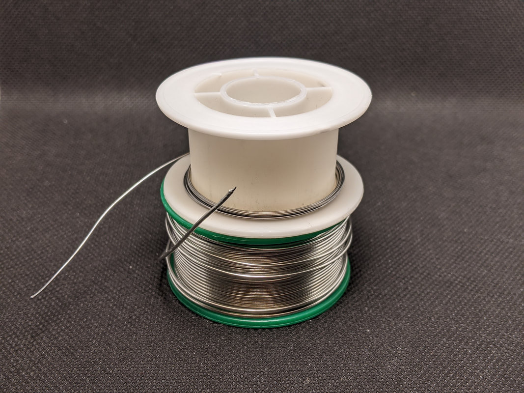
Solder
The material that is melted to join electrical components. It is usually in a wire form and is made of either lead/tin (leaded) or silver/tin (lead-free). Many solders also include a rosin core, eliminating the need of a rosin pen. |
|
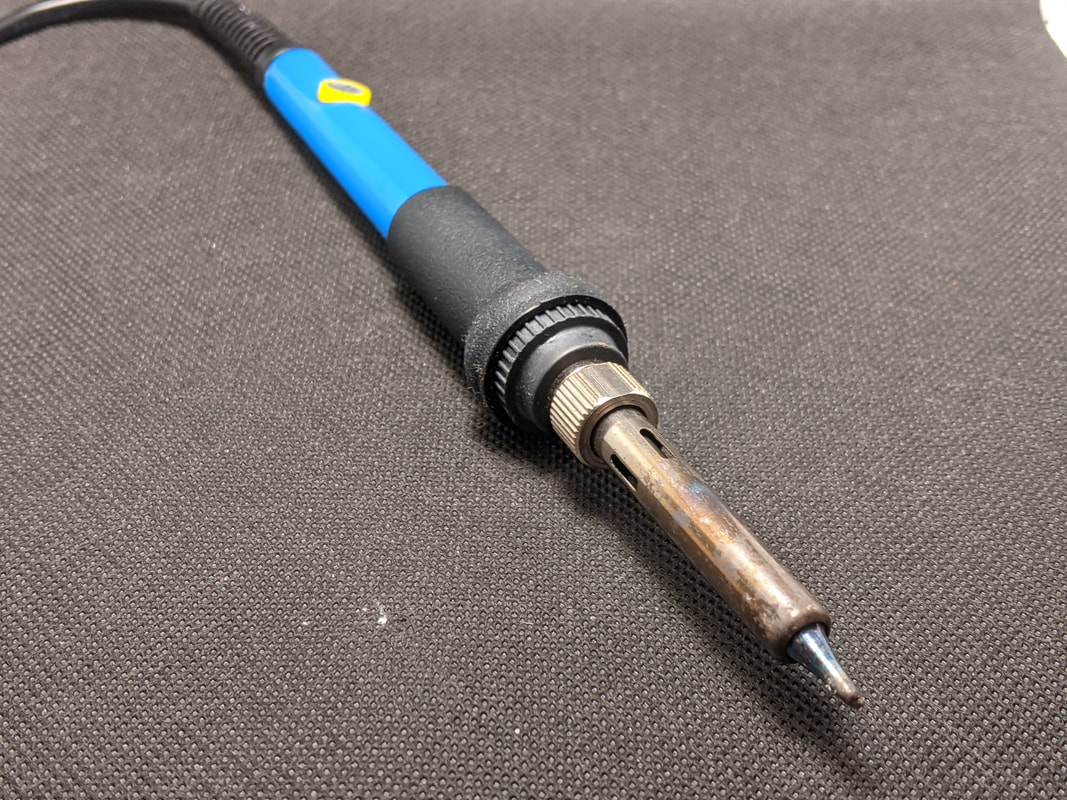
Soldering Iron
The soldering iron is used to heat the solder as it is applied. The iron is also sometimes connected to a soldering station that controls the exact temperature, but many low-cost irons include this functionality directly inside. |
|
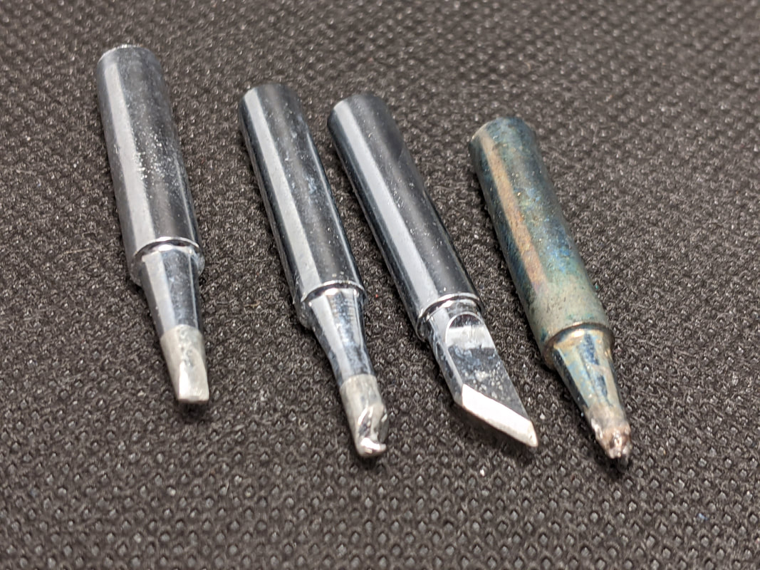
Soldering Tip
Most soldering irons have a removable tip, and there are different styles of tips for different uses. For soldering through-hole components like this kit, I recommend a fine cone or pointed soldering tip, but nearly any shape will work. |
|
Rosin / Flux
Rosin (sometimes called flux) is used in soldering to help the liquid solder flow smoothly and stop the solder or its contact point from oxidizing. Most solder has a rosin core, so there is no need to worry about this. If you are using solder with no rosin core, you will need to add rosin to the board with a rosin pen before soldering. |
|
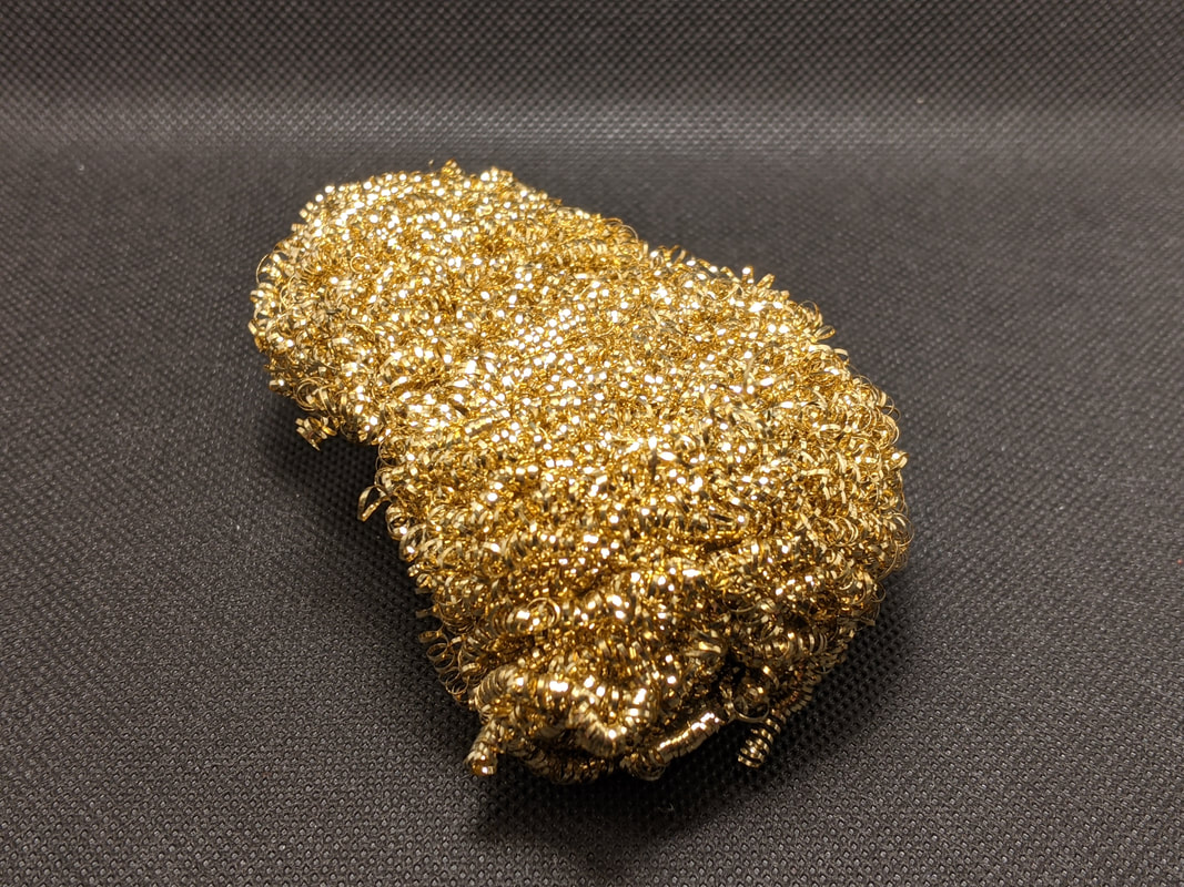
Tip Cleaner
Removes oxidized material and excess solder from the tip of your iron. It is either a wet sponge or brass sponge. |
|
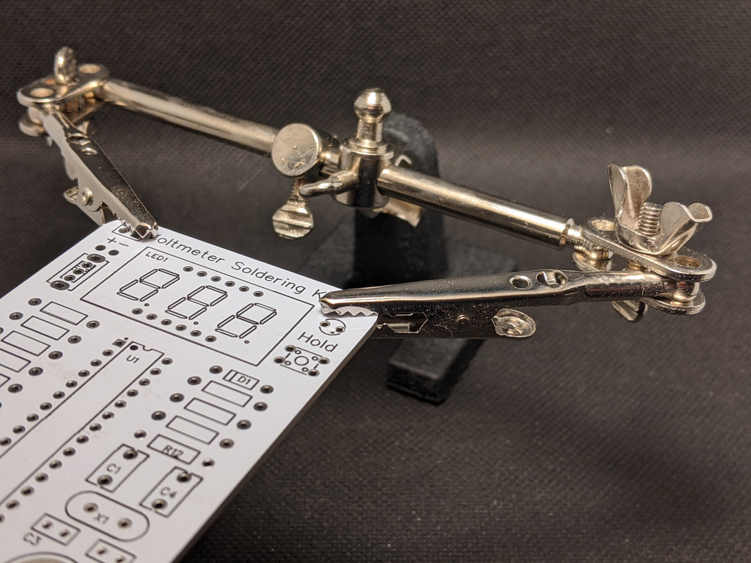
Helping Hand / Board Holder
To make it easier to solder, many people use a board holder or helping hand. These are tools that will hold your board at a useful angle to make soldering more convenient. While they are not necessary, they do make life a lot easier, especially when you have hundreds of solder connections to make. |
|
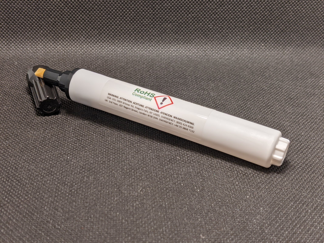
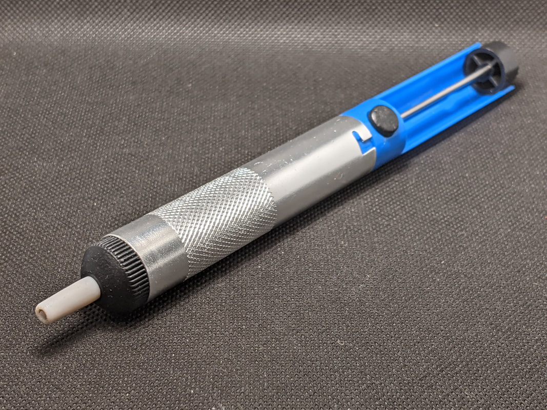
Solder Sucker / Solder Plunger
A solder sucker, sometimes called a solder plunger, is used to remove solder from a connection if we want to undo one of our joints. It uses a spring-loaded plunger to suck the liquid solder up inside, away from the board. While it will not get 100% of the solder, it removes a large portion of it. |
|
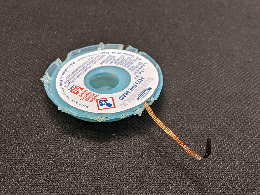
Solder Wick
Usually used after a solder sucker, solder wick removes any remaining solder from an electrical joint. To use it, just place it over the solder and put your soldering iron on top. When the solder melts, it will get wicked up into the solder wick, and the wick will change from a copper-orange to a silver color. Once the wick has solder in it, you need to cut off that section and use a new part of the wick. Be careful, the wick gets very hot very quickly when in use, only hold it from the plastic spool it came on. |
Through-Hole Soldering
This kit will be looking at a style of soldering called through-hole, commonly abbreviated to THT (with the third “T” being for technology). As the name implies, one component will have a lead, or extended metal part, that goes through a hole in the other part. Solder then flows in between the two to make a solid connection. You can tell if a part is THT soldered if there is a bit of metal sticking out the bottom of the PCB. On your Arduino, all of the pin headers will be through-hole soldered.
How to Make a Through-Hole Solder Joint
We will now go through how to make a through-hole solder joint. The same process applies for any package or component. We will go over how to apply this technique to each specific package type as we work through the soldering kit. In general, the entire process of soldering a THT joint should take less than 10 seconds. If you heat the board or component for too long, there is a risk of damage. One thing to keep in mind is that not all pins will take the same amount of time to solder. Specifically, pins connected to copper pours (5V and GND in this kit) will take significantly longer to solder, as the heat will be dissipated to the pour instead of concentrating in the pin.
|
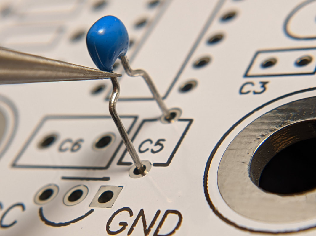
Align the component and push the leads through the holes of the board. For some components, like resistors, you will have to bend the leads to fit into the board. Components like LEDs and capacitors should be fine as-is.
|
|
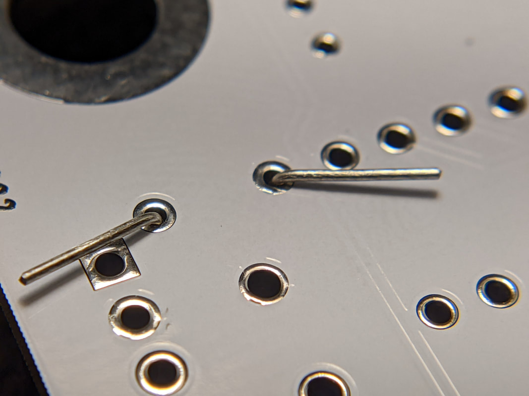
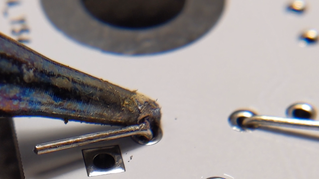
Bend the leads over on the back to secure the part in place.
|
|
Apply your soldering iron to the pad and the lead of the component. For most THT parts, you solder on the opposite side of the board from where you put the part through.
|
|
Press the solder wire up against the lead and pad, so that it begins to heat as well. Do not place the solder wire on top of the iron, or else the solder will just stick to the iron.
|
|
When the solder starts melting, push the solder wire forward a bit to add some more solder to the joint.
|
|
Remove the soldering wire. Wait one second, then remove the soldering iron. The solder should have flown fully around the pin.
|
|
If the solder did not fully flow around the pin, you can try "reflowing" the solder by applying the iron so it liquefies. If that still does not do the trick, you can add a bit more solder.
|
Troubleshooting Soldering Issues
|
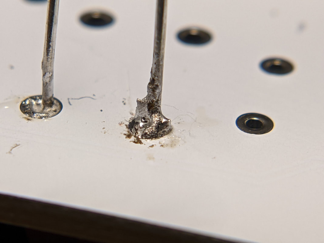
Grey / Cold Joint
Cold joints are caused by not enough heat fully melting the solder. Increase the temperature of your iron or keep it on the pad for longer. |
|
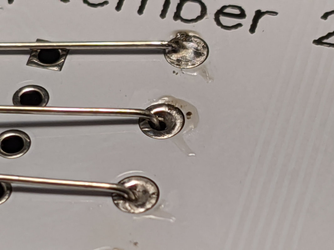
Not Enough Solder
If the solder does not fully wrap around the pin, add more by heating it up and melting more solder wire into it. |
|
Too Much Solder
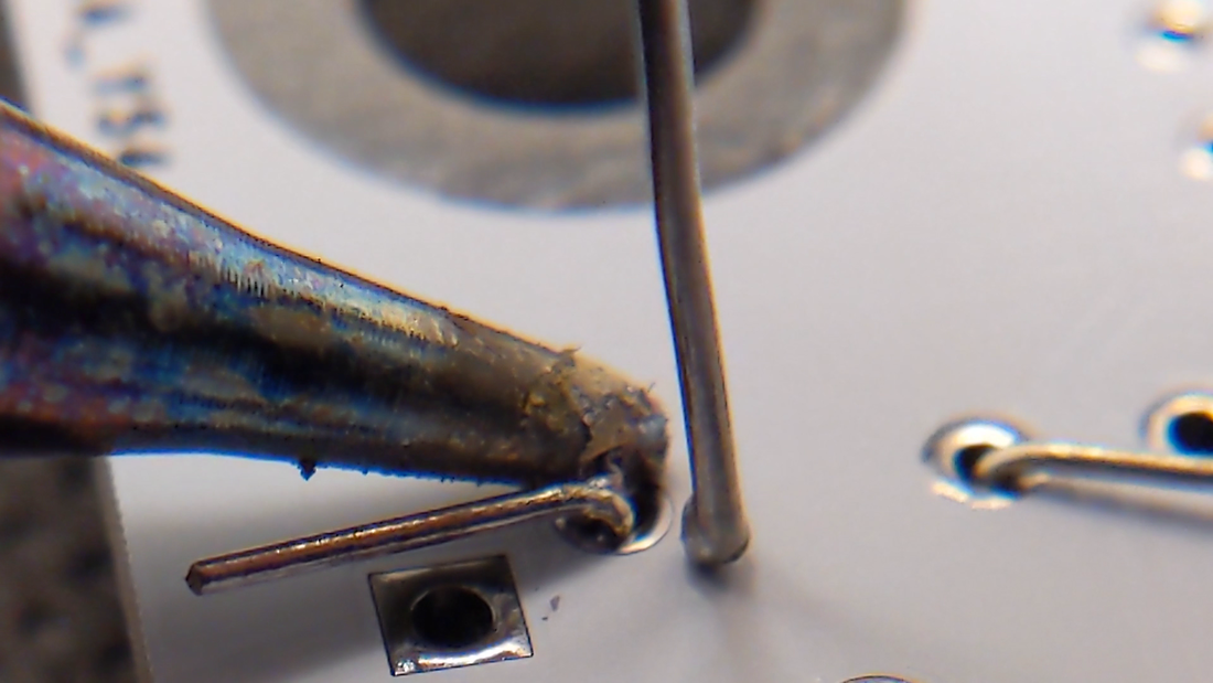
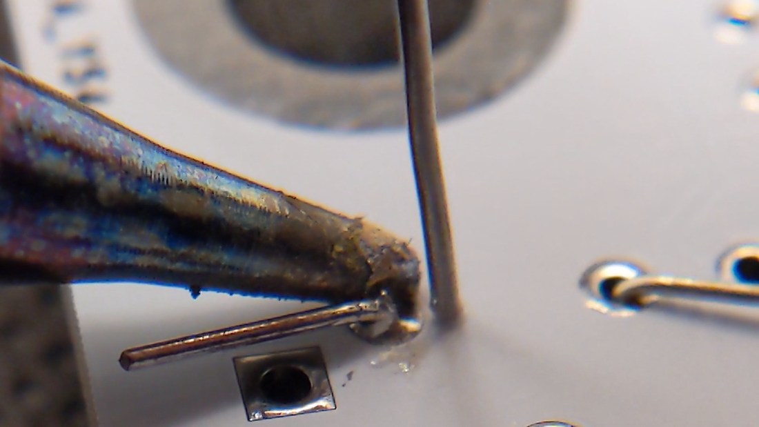
If there is too much solder on the pin, it may bridge or break off and short something. Remove excess solder with a solder sucker. |
|
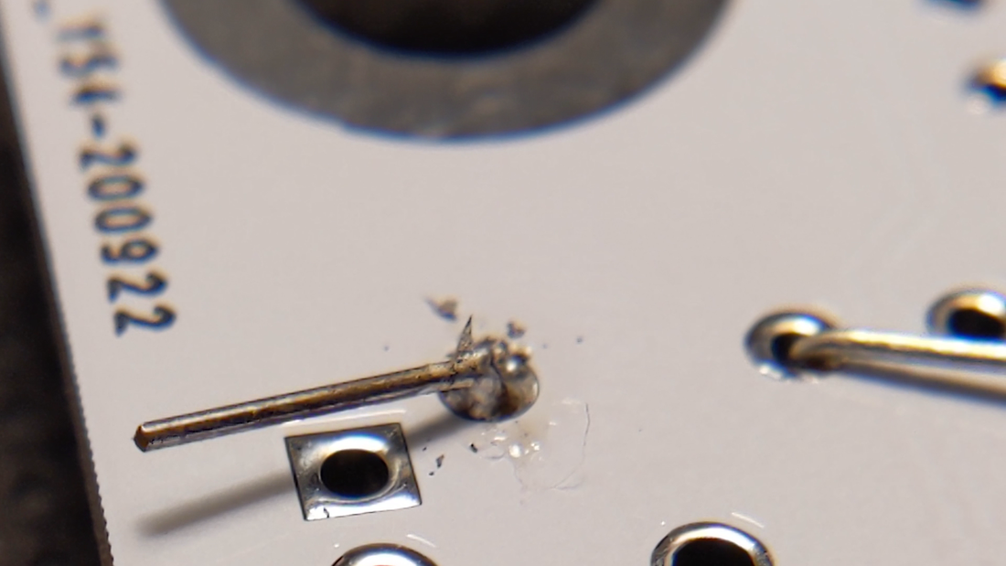
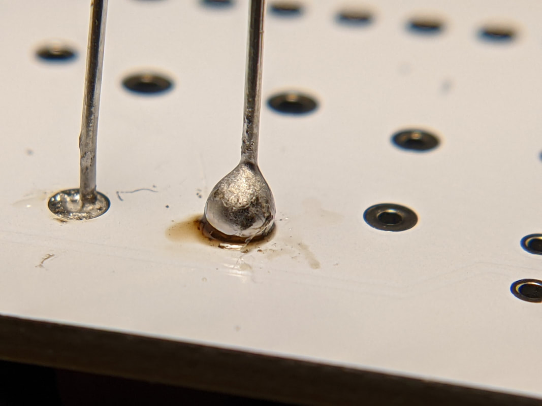
Burn Marks on PCB
This burning is most likely just burned rosin. It can be removed with a paper towel or Q-tip and a bit of isopropyl alcohol. |
|
|
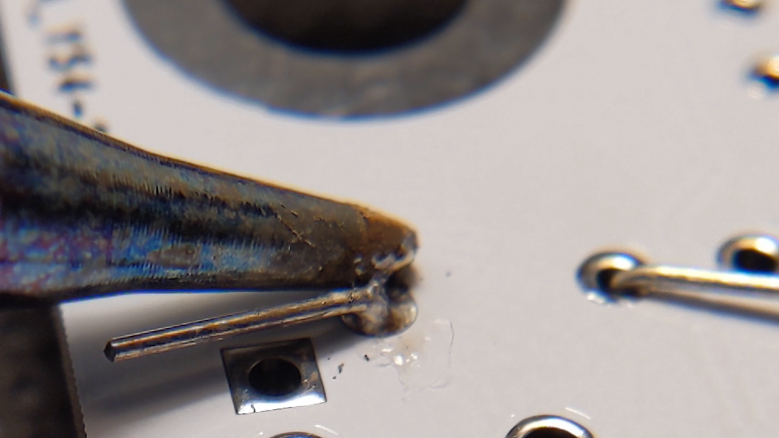
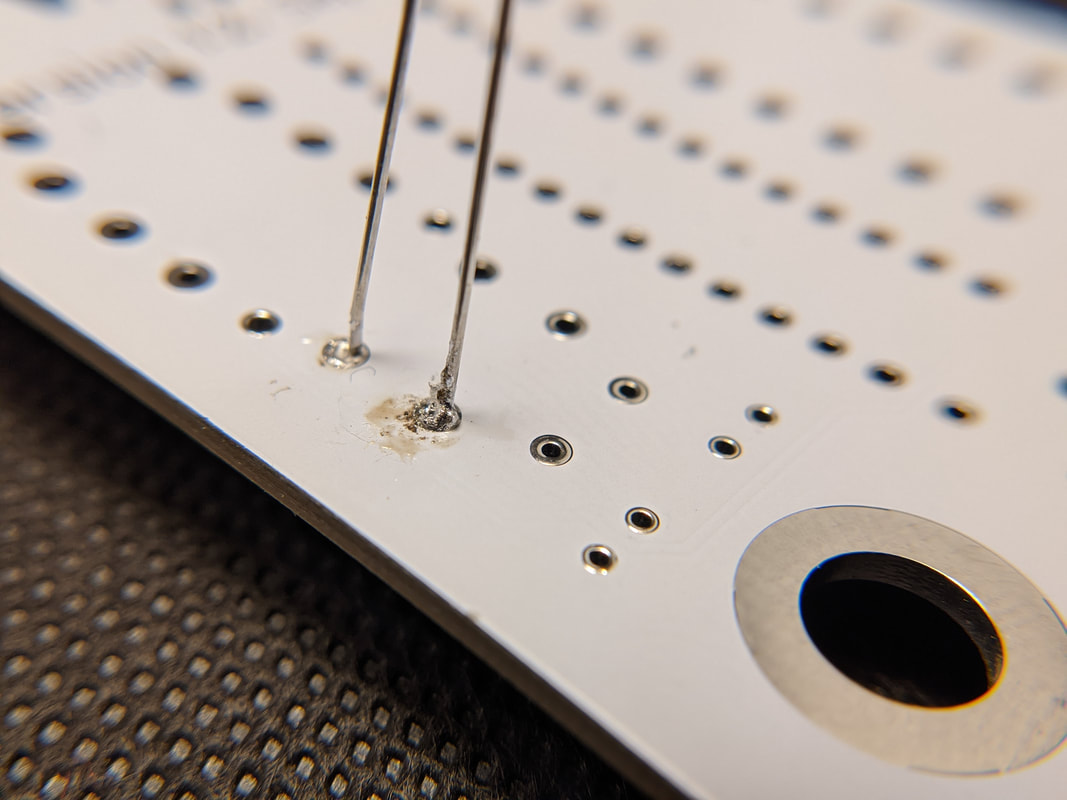
Spiky Solder Joint
If the iron is too hot or too cold, the solder will form a sharp point as you pull it away. This can be fixed by modifying the temperature. |
|
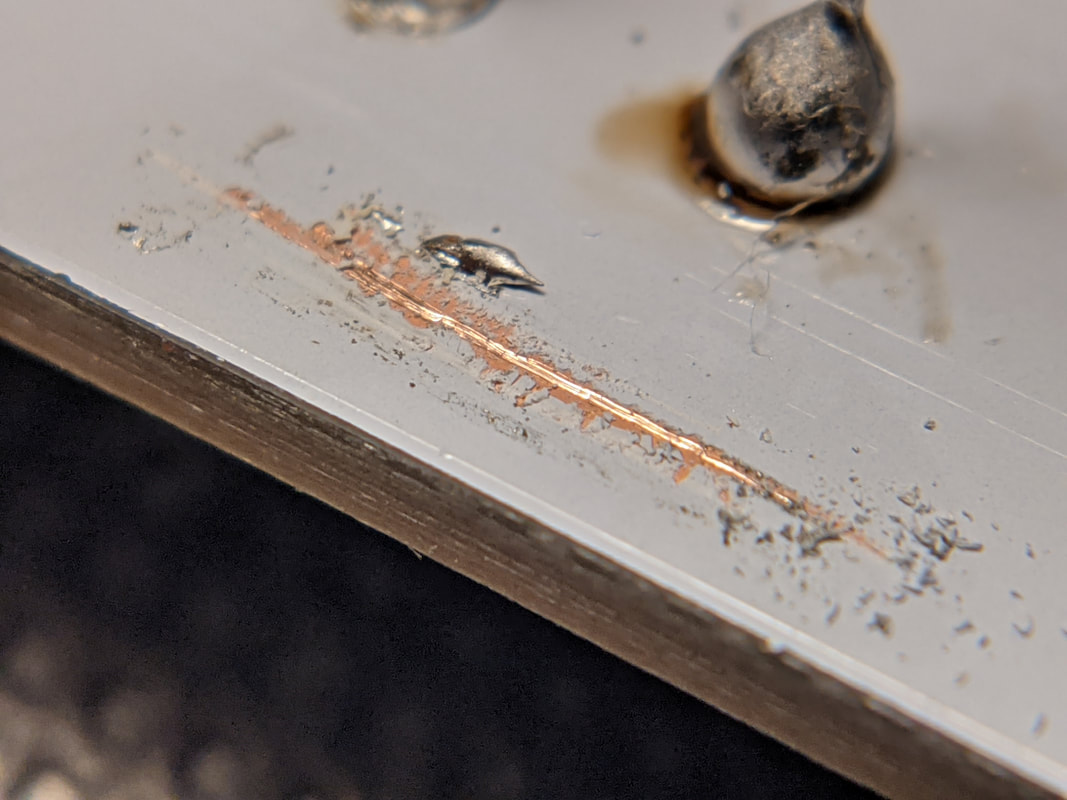
Damage to Silkscreen
If the silkscreen is damage and copper below is exposed, be careful not to get any solder on it. Cover any exposed copper with nonconductive tape or glue. |
Tips for Making Soldered Projects Look Better
Even if you solder everything correctly, sometimes your board will come out looking a bit weird. Here are a few tips to make your assembled project look much cleaner and more professional. None of this will have any impact on the operation of the circuit, just how it looks.
- Align similar components. If you have multiple identical components in a row (like the resistors up the left side of the voltmeter), arrange them all to be in the same orientation.
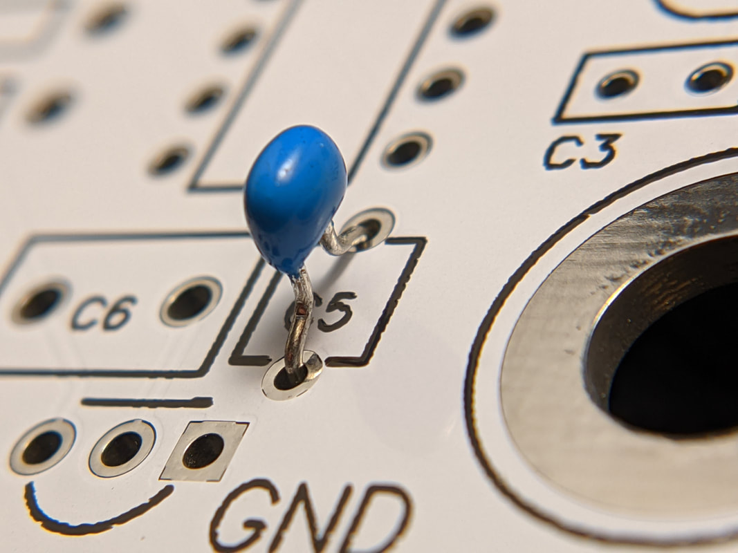
- Keep parts inline with the silkscreen. As you connect a part, make sure that it lines up cleanly with the silkscreen below. My go-to trick to do this is to solder one lead, then re-heat the solder on that pin as I gently push the component perpendicular to the board, so both leads press against the same edge of their respective holes. This will make sure that the part is parallel with the silkscreen, without having to try and line it up by hand. Keep in mind that the part will get hot when you heat up one lead, so be careful!
- Clean around solder joints. The rosin from solder joints will build up in translucent films around solder joints, that catch the light at odd angles. You can remove this with isopropyl alcohol and a toothbrush or Q-Tip.
Further Reading
Looking for more tips on how to solder? I'd suggest reading Sparkfun's guide on THT soldering. It contains a ton of great information!