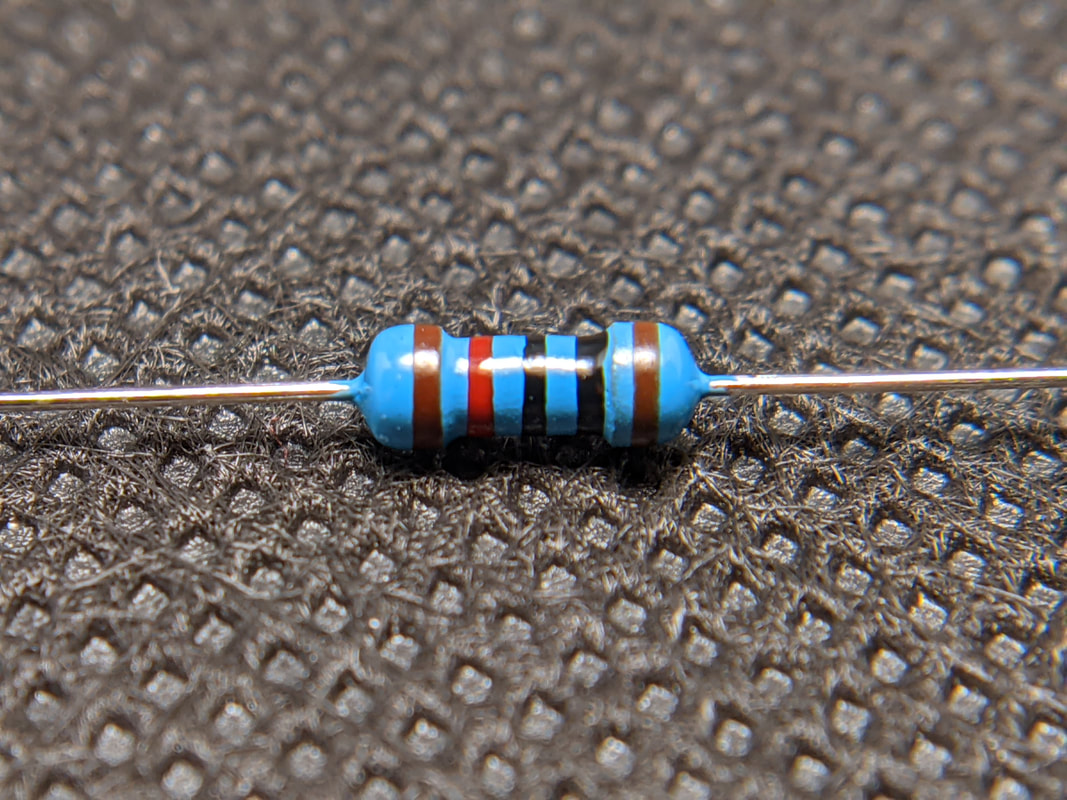
WARNING: Similar-Looking Components
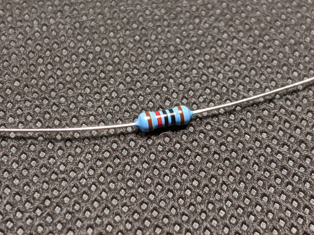
Resistors will always look very similar, make sure you are using the correct one for each step (designated by the colored bands on the side, see Section 2 for more information). Be extra careful of steps 1 and 3! 10k resistors and 120 resistors look nearly identical! The 120 resistors will be on a tape reel in Bag 3 with the PCB, the 10k resistors will be loose in Bag 1.
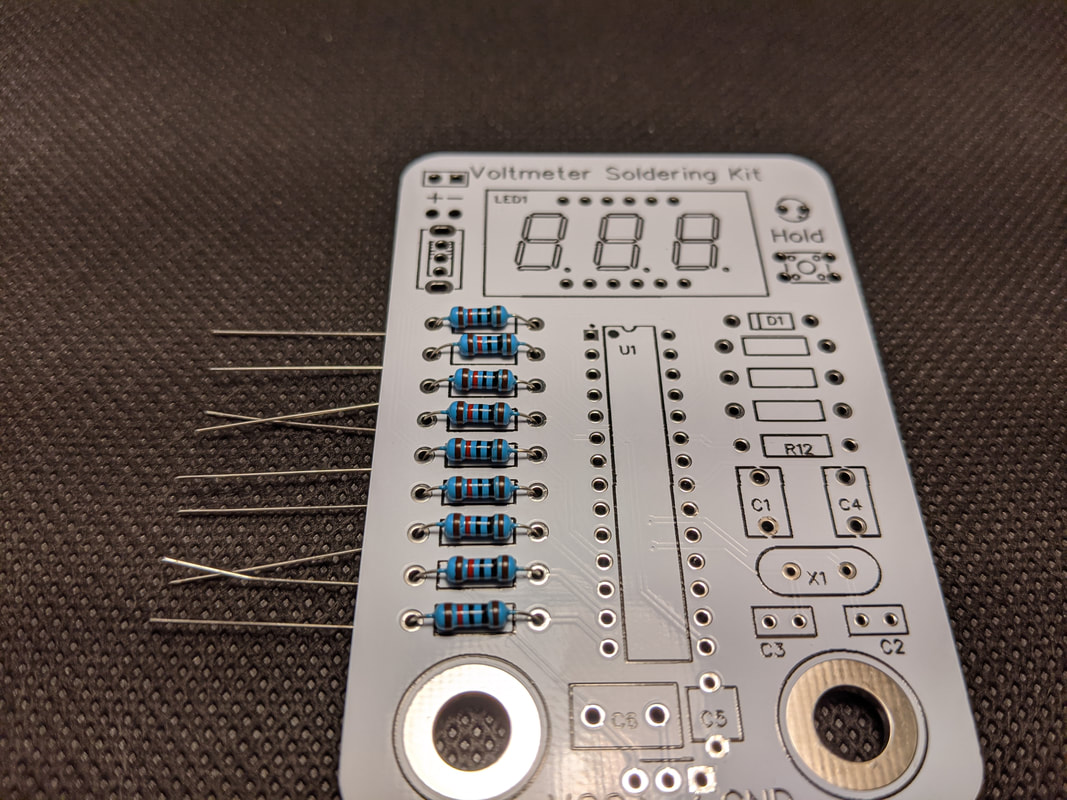
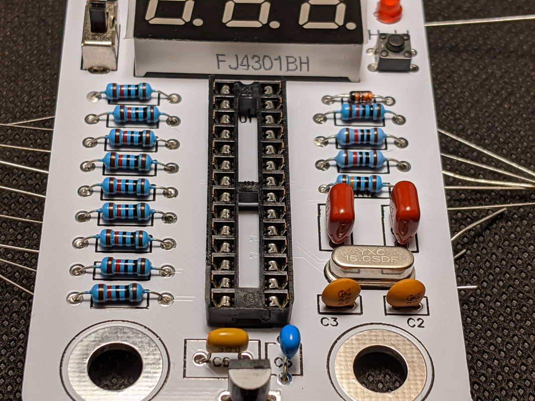
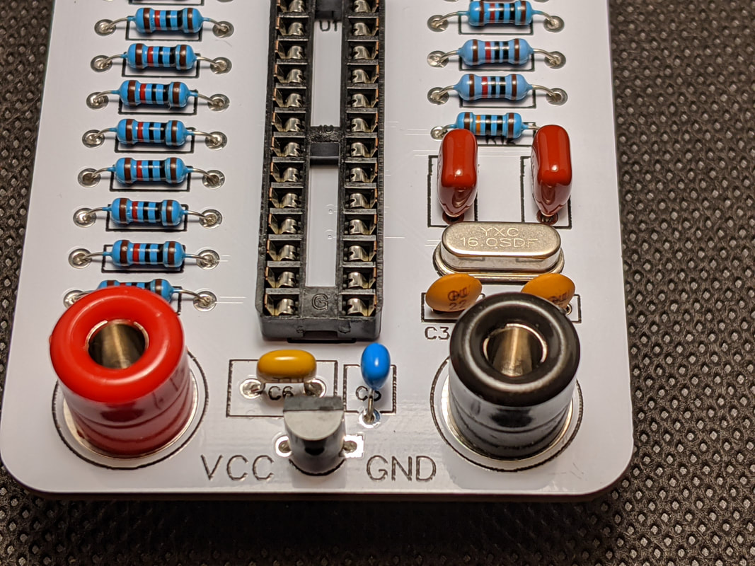
Step 1: Current-Limiting Resistors
Solder the 9 current-limiting resistors on the left side of the board. These should be the resistors that come on a tape reel in the same bag as the PCBs. Since they are resistors, the orientation does not matter, but it is suggested that you keep them all in the same orientation for aesthetics.
|
|
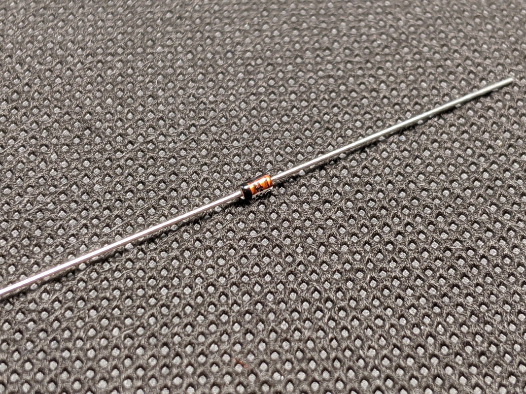
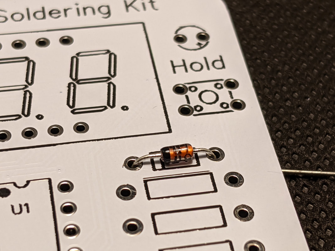
Step 2: Battery Diode
Solder the battery protection diode from Bag 1 on the right of the board. Make sure it is installed in the proper orientation! One side of the diode is black, this side should to to the left, matching the location of the bar on the silkscreen.
|
|
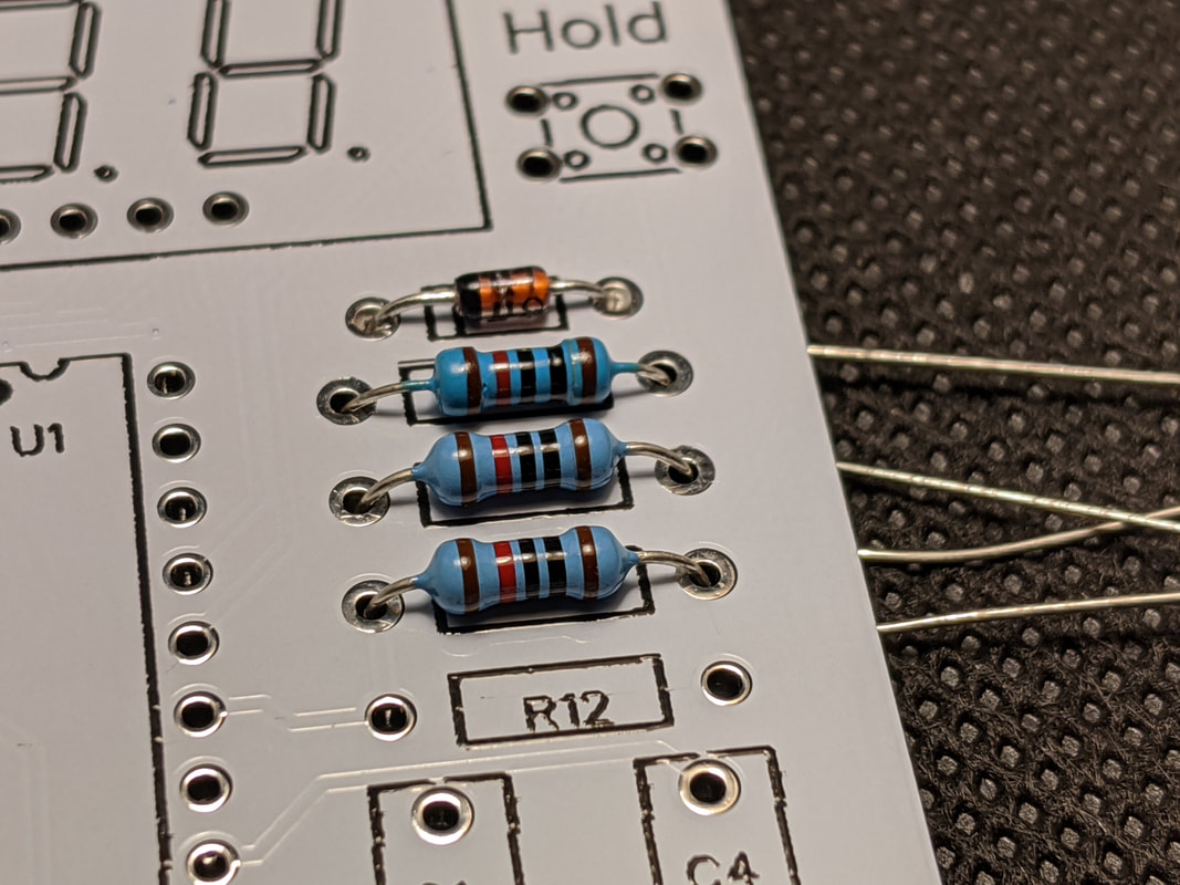
Step 3: 10k Resistors
Solder 3 of the 10k ohm resistors from Bag 1 onto the right side of the board, under the battery diode. Like before, the orientation does not matter, but keeping it consistent helps make everything look better. The 10k resistors will be the ones in Bag 1 with a red band second from one edge. The orange band one, the 100k ohm resistor, will be used in the next step.
|
|
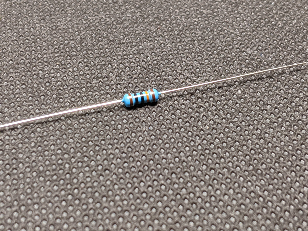
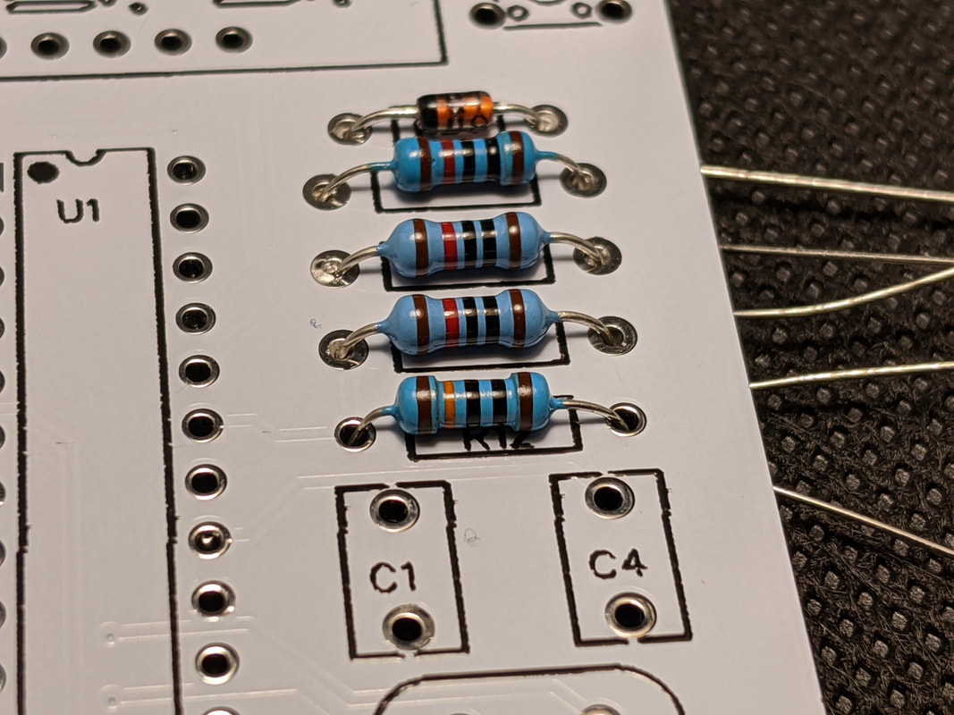
Step 4: Divider Resistor
Solder the 100k ohm divider resistor from Bag 1 on the right side of the board, in the spot labeled "R12" on the silkscreen.
|
|
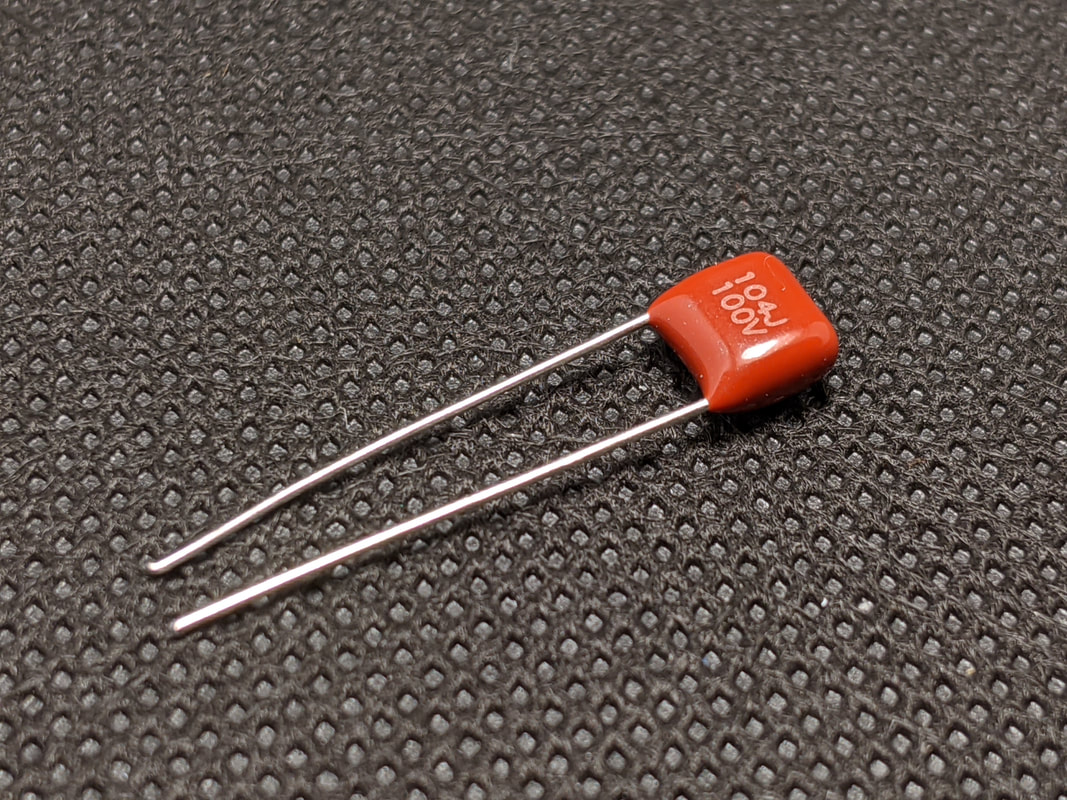
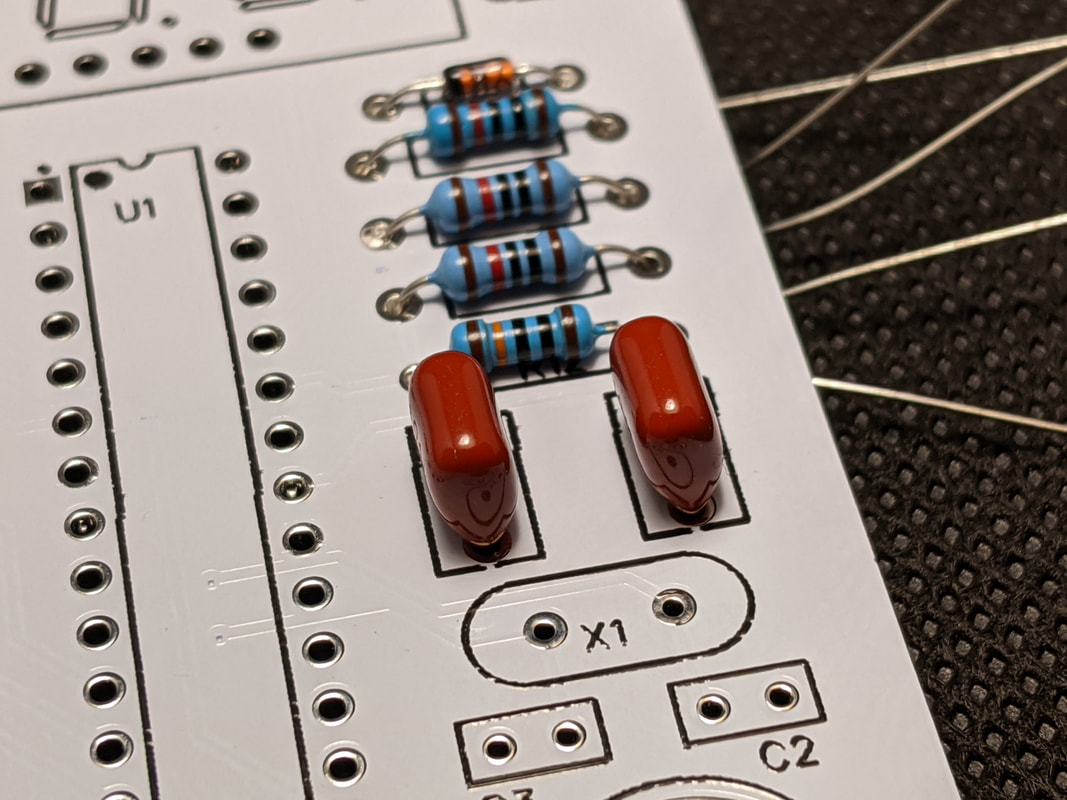
Step 5: MCU Capacitors
Solder the two 100nF capacitors from Bag 1 on the right of the board, in the spots labeled "C1" and "C4." These are the large burgundy capacitors, and orientation does not matter.
|
|
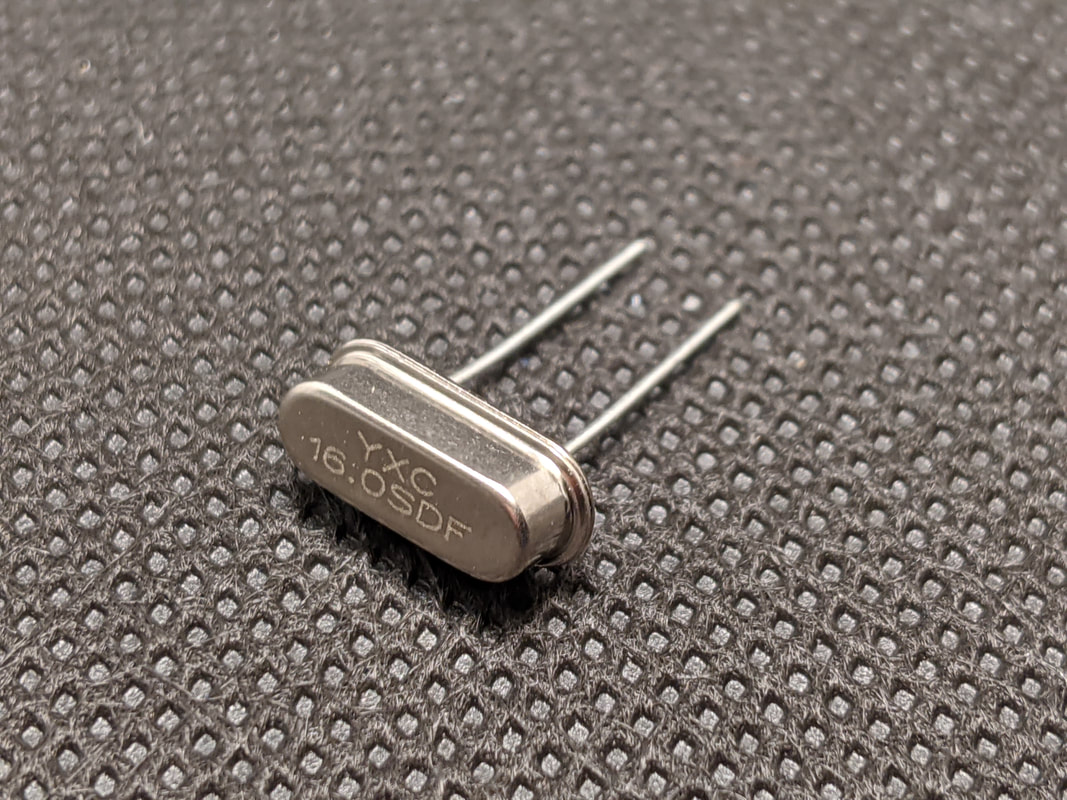
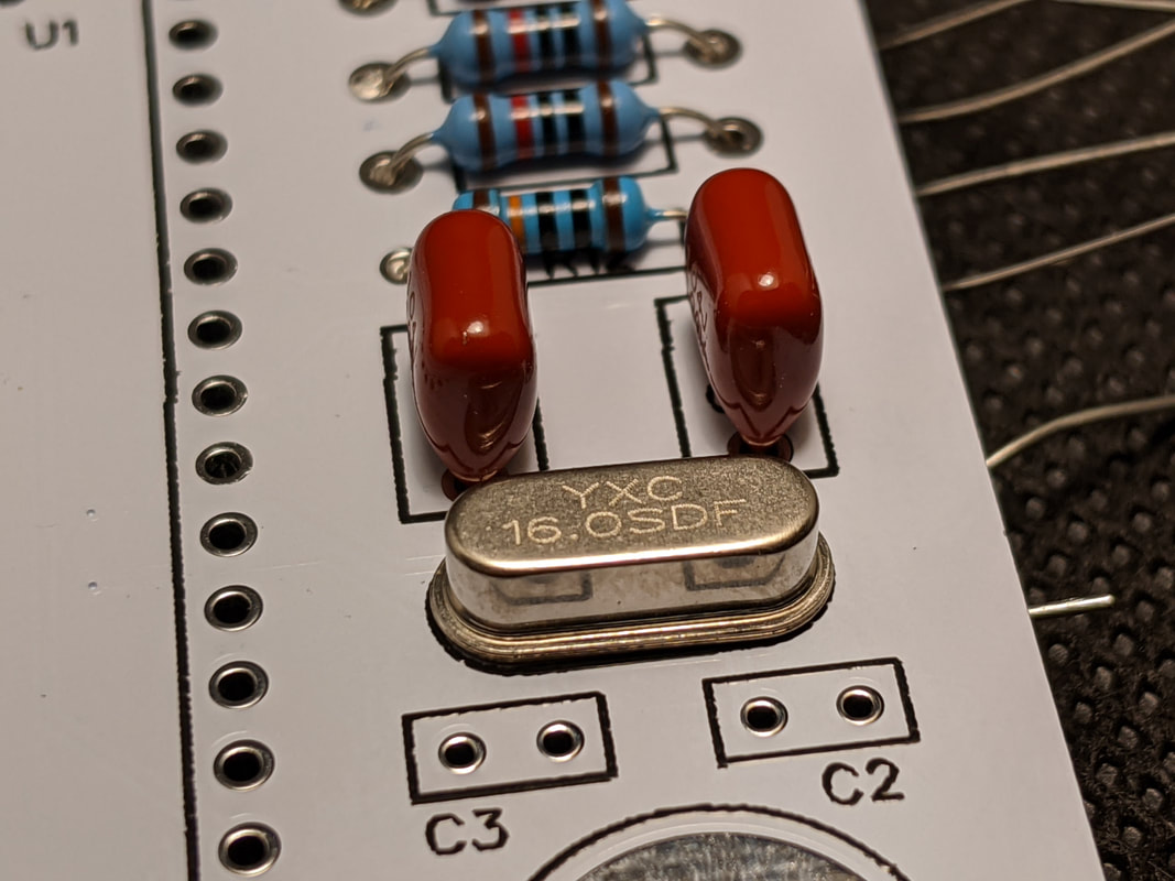
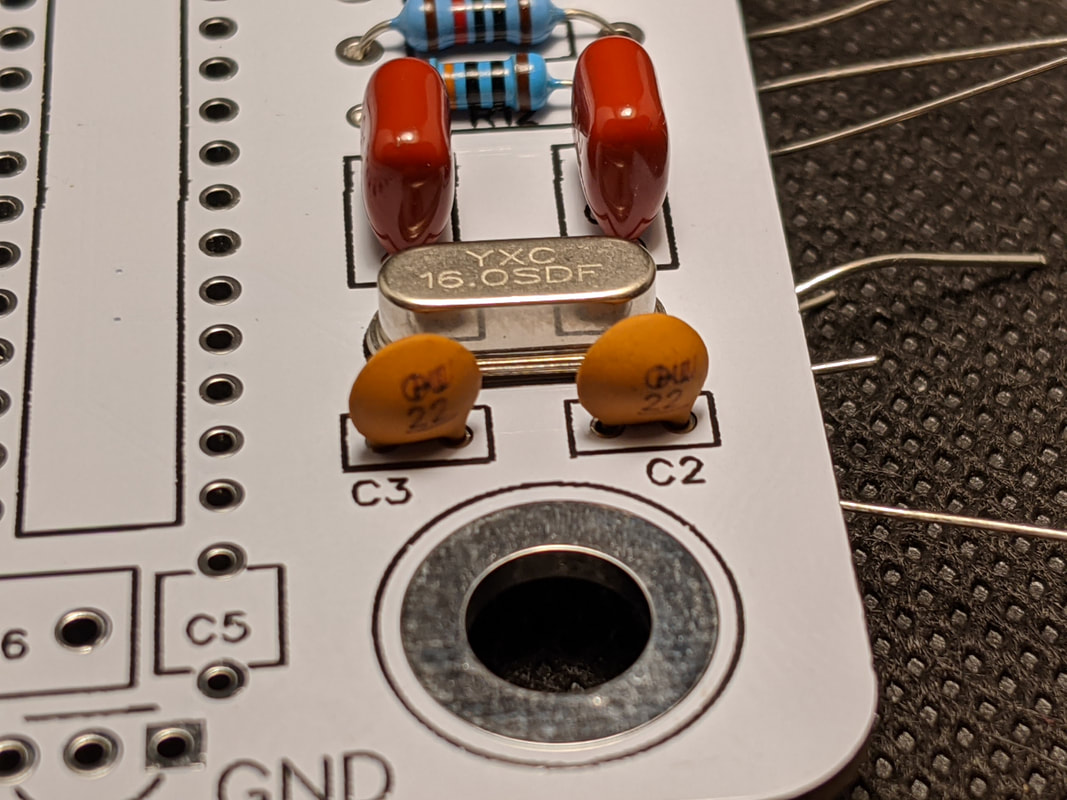
Step 6: Crystal Resonator
Solder the crystal resonator from Bag 1 in the spot labeled "X1" on the right of the board. The orientation does not matter, but it is usually best practice to mount it so the writing on the top is the right way around.
|
|
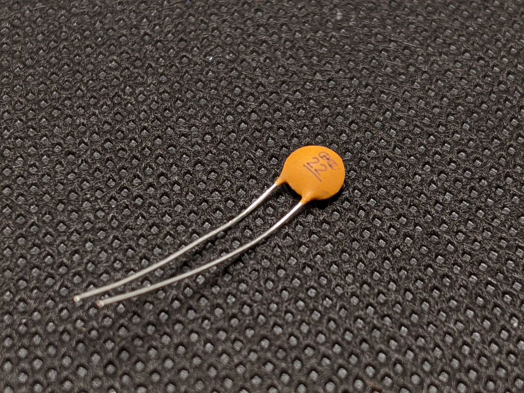
Step 7: Resonator Capacitors
Solder the 2 22pF resonator capacitors from Bag 1 at "C3" and "C2." These are the small tan circular parts. Like the other capacitors in this kit, orientation does not matter.
|
|
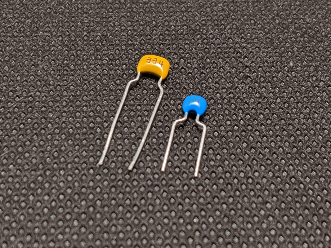
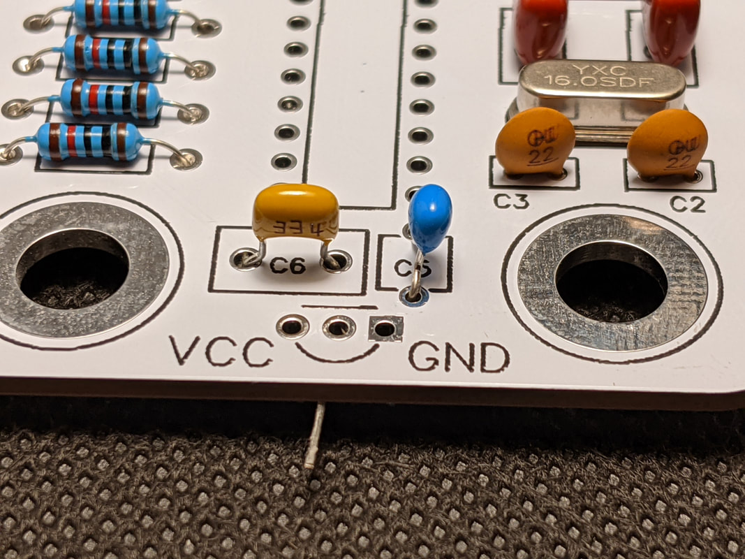
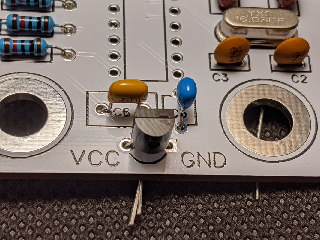
Step 8: Regulator Capacitors
Solder the two capacitors for the voltage regulator from Bag 1 at the bottom of the board. C6 should be the 330nF tan rectangular capacitor, and C5 should be the 100nF blue semicircle capacitor. The leads for these capacitors have a bend in them to they sit off the PCB a bit, do not try to straighten them out as you install them!
|
|
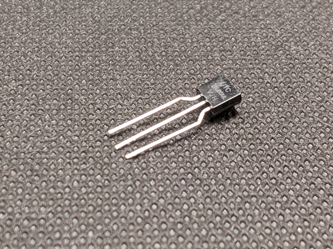
Step 9: Voltage Regulator
Solder the voltage regulator from Bag 1 to the bottom of the board. Make sure that the curve of the TO-92 package matches the curve on the silkscreen!
|
|
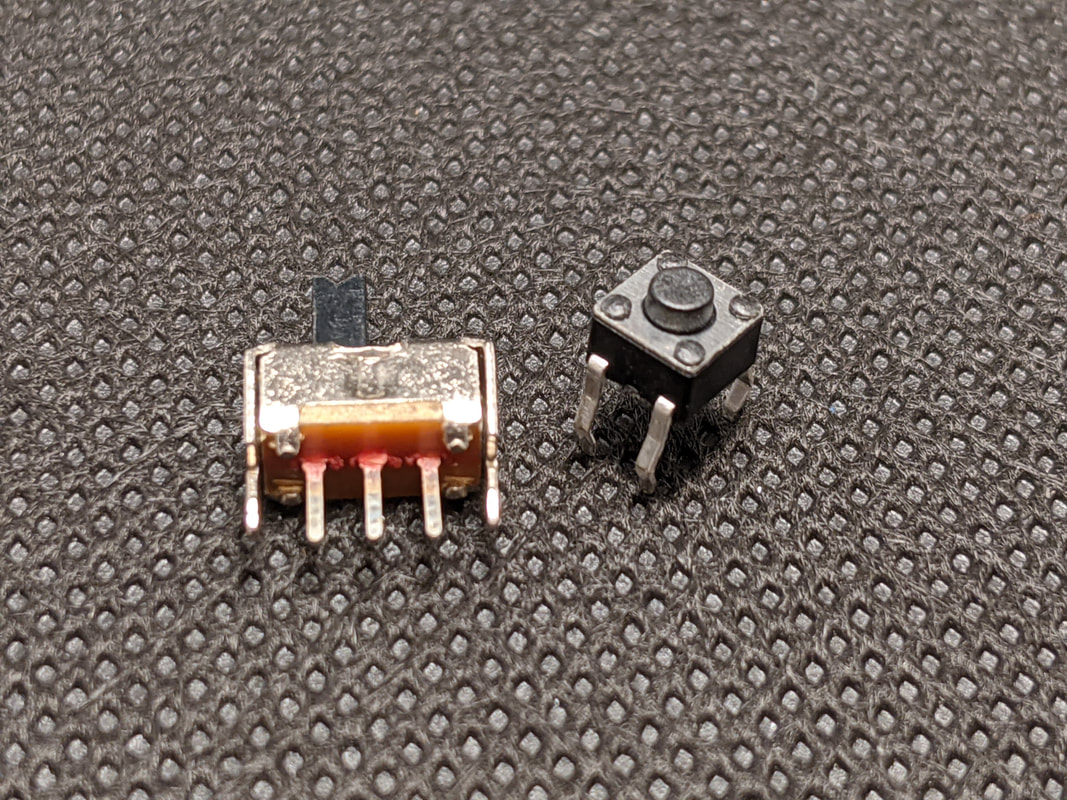
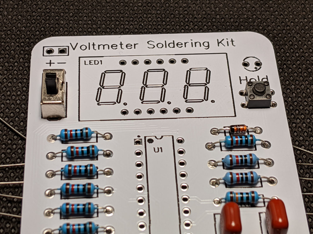
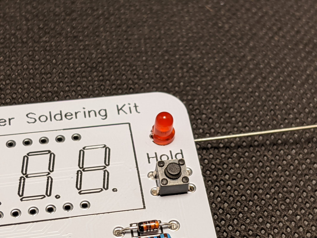
Step 10: Switches
Solder the momentary switch on the right of the board, and the toggle switch on the left. The two larger pins on the outside of the toggle switch are to hold down the housing, so soldering them will heat up the outside of the switch, be careful! Both of these can be found in Bag 1.
|
|
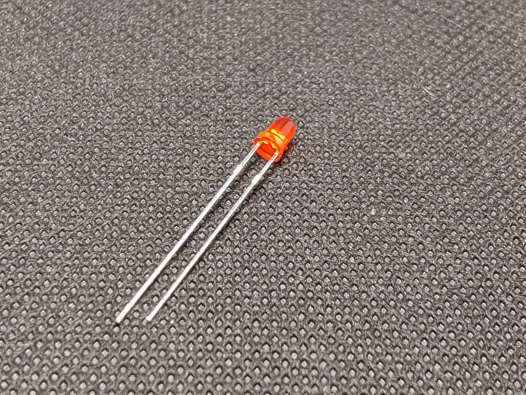
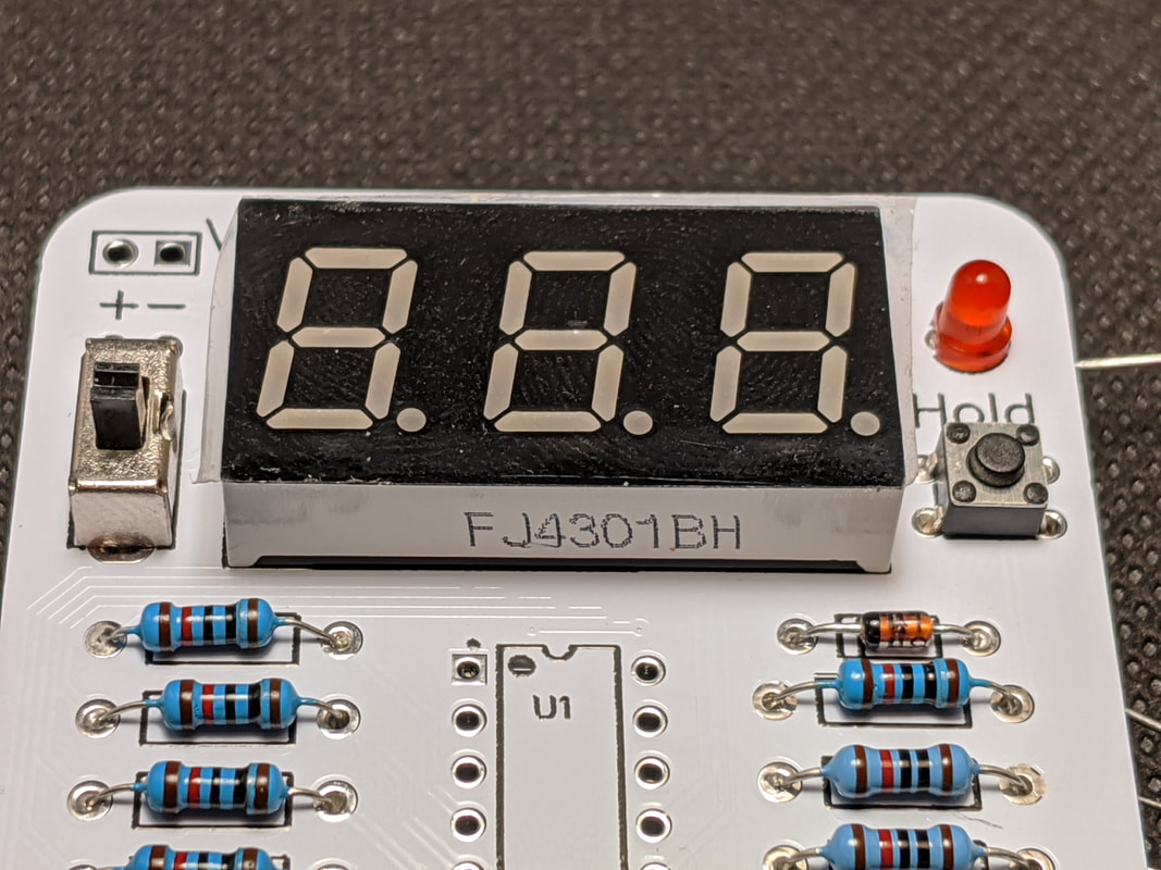
Step 11: LED Indicator
Solder the LED indicator from Bag 2 in the top right corner of the PCB. The longer lead of the LED should go in the hole on the right, marked with a "+" sign.
|
|
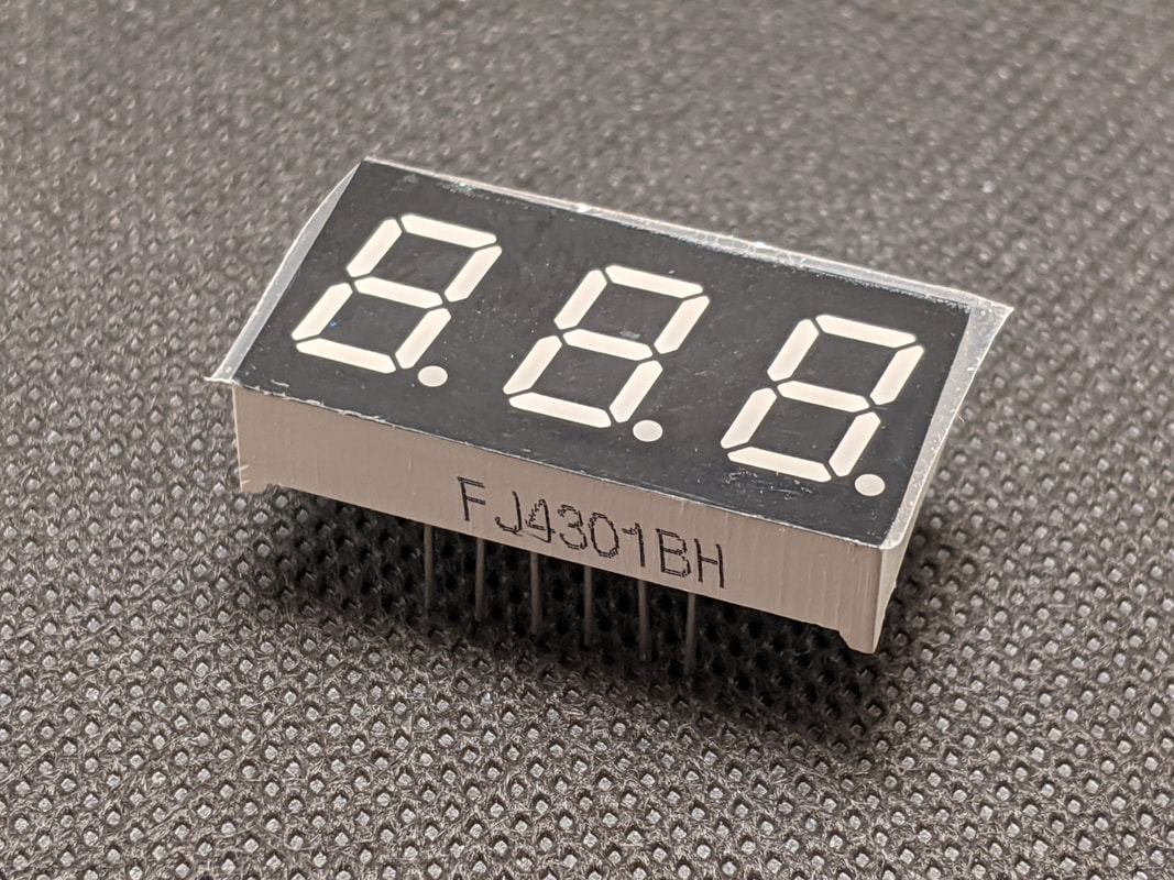
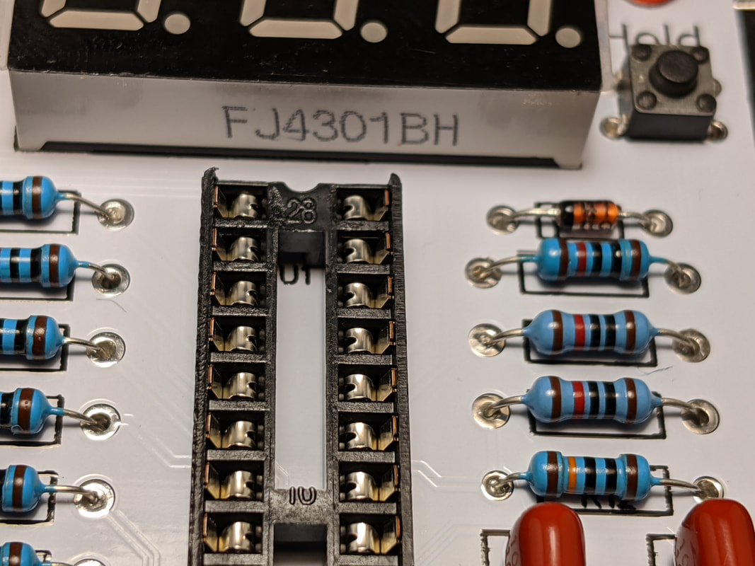
Step 12: 7-Segment Display
Solder the 7-segment display from Bag 2 onto the top of the PCB. The pins on this part are very long and thin, so they may have bent during shipping. If the part does not line up, bend the leads into their respective holes by hand. Make sure that the numbers are the right way up and the bottom of the display is against the PCB before soldering. Depending on the version of 7-segment display your kit includes, there may be 1 hole that does not have a corresponding pin. Do not worry about that, it will still work the same.
|
|
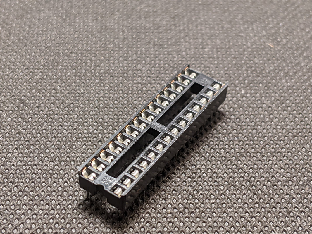
Step 13: DIP Socket
Solder the 28-pin DIP socket from Bag 2 in the center of the board. The small groove on the socket should match the small groove printed on the silkscreen.
|
|
|
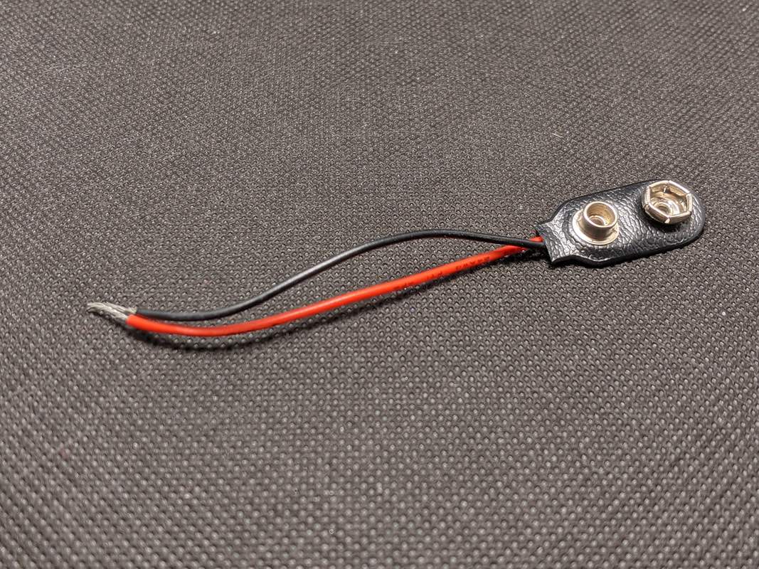
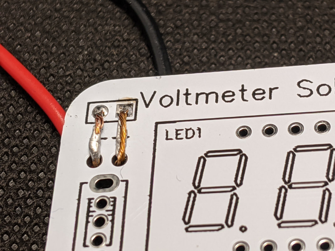
Step 14: Battery Clip
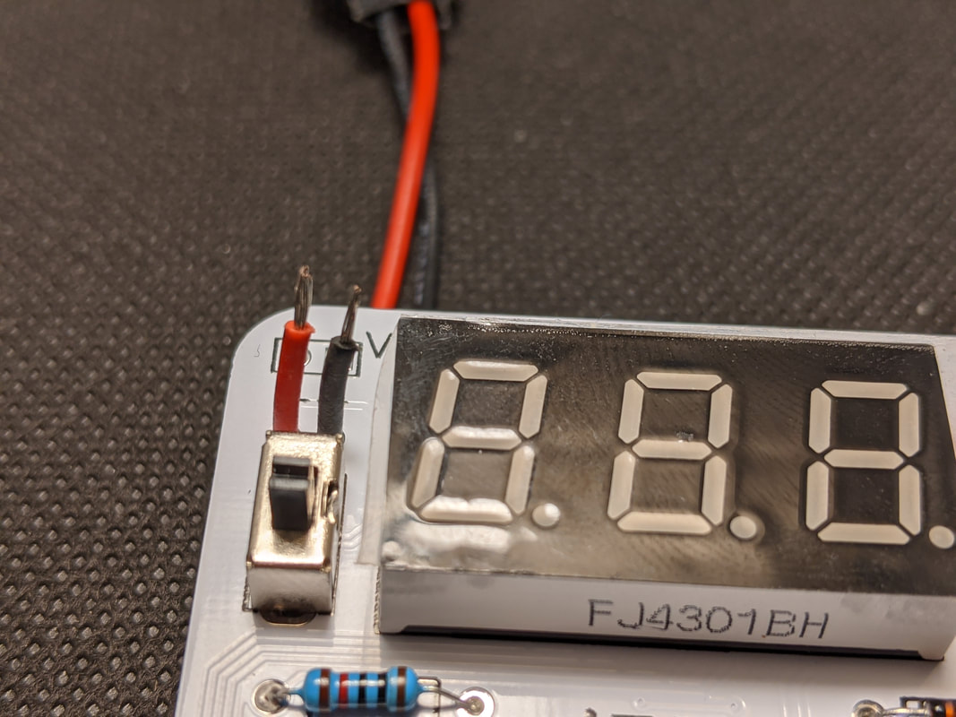
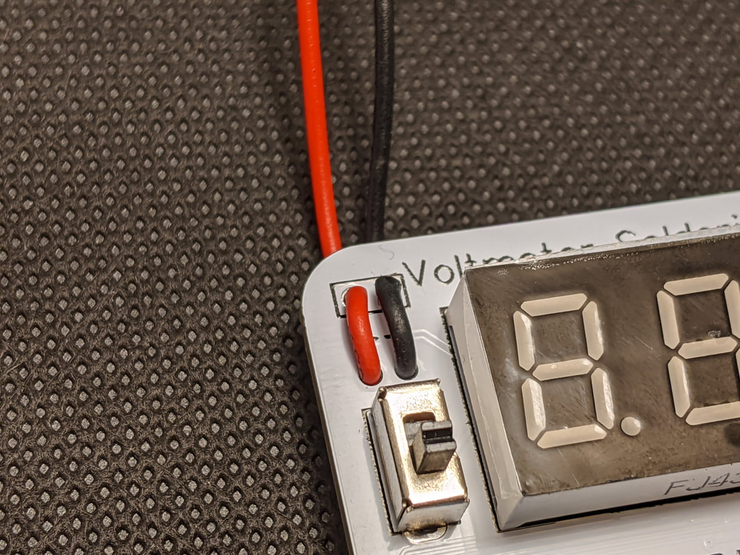
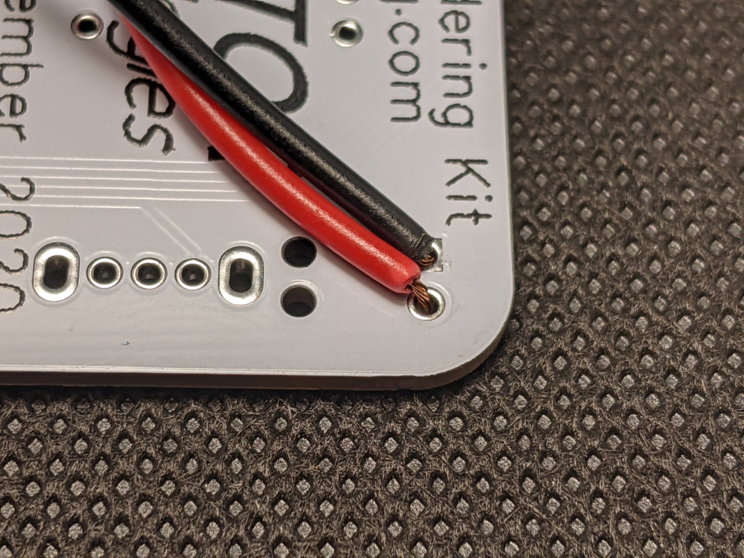
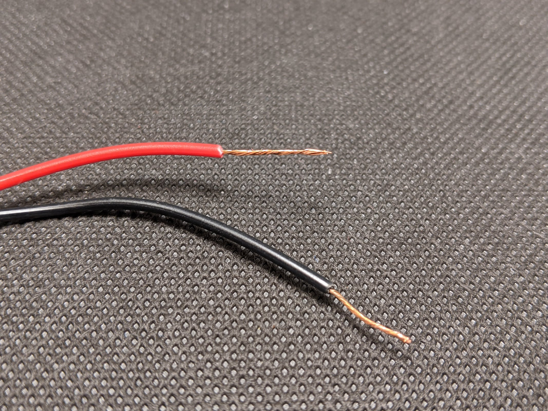
Push the wires of the battery clip (from Bag 2) through the holes in the top left of the PCB from the back, making sure that the red wire comes out the hole next to the "+" sign, and the black wire next to the "-" sign. The wires are a very tight fit, you will have to twist the wires as you push them through for it to work. If the insulation on the wire is bent or damaged, you may need to trim it a bit to fit through the holes. Pull the wires out approximately 1/2 of an inch, then bend them over and put the bare end of the wire through the metal holes in the board. Solder the wires from the underside, then pull gently on the wires from the bottom to pull back the excess slack from the top.
|
|
|
Having trouble getting the battery wires through the PCB?
The fit on the wires and the hole on the PCB is very tight - proper installation may require deforming the wire's insulation! If you are struggling to get the wires installed as listed above, here are a few alternatives:
The fit on the wires and the hole on the PCB is very tight - proper installation may require deforming the wire's insulation! If you are struggling to get the wires installed as listed above, here are a few alternatives:
Alternative 1: Mount from the bottom
If you want, you can bypass the strain relief altogether and push the wires up from the bottom to solder them. Keep in mind that this may lead to fatigue on the wires, so you may want to put a small amount of glue over the wires, and only use the voltmeter like this if you are attaching the battery to the back!
If you want, you can bypass the strain relief altogether and push the wires up from the bottom to solder them. Keep in mind that this may lead to fatigue on the wires, so you may want to put a small amount of glue over the wires, and only use the voltmeter like this if you are attaching the battery to the back!
|
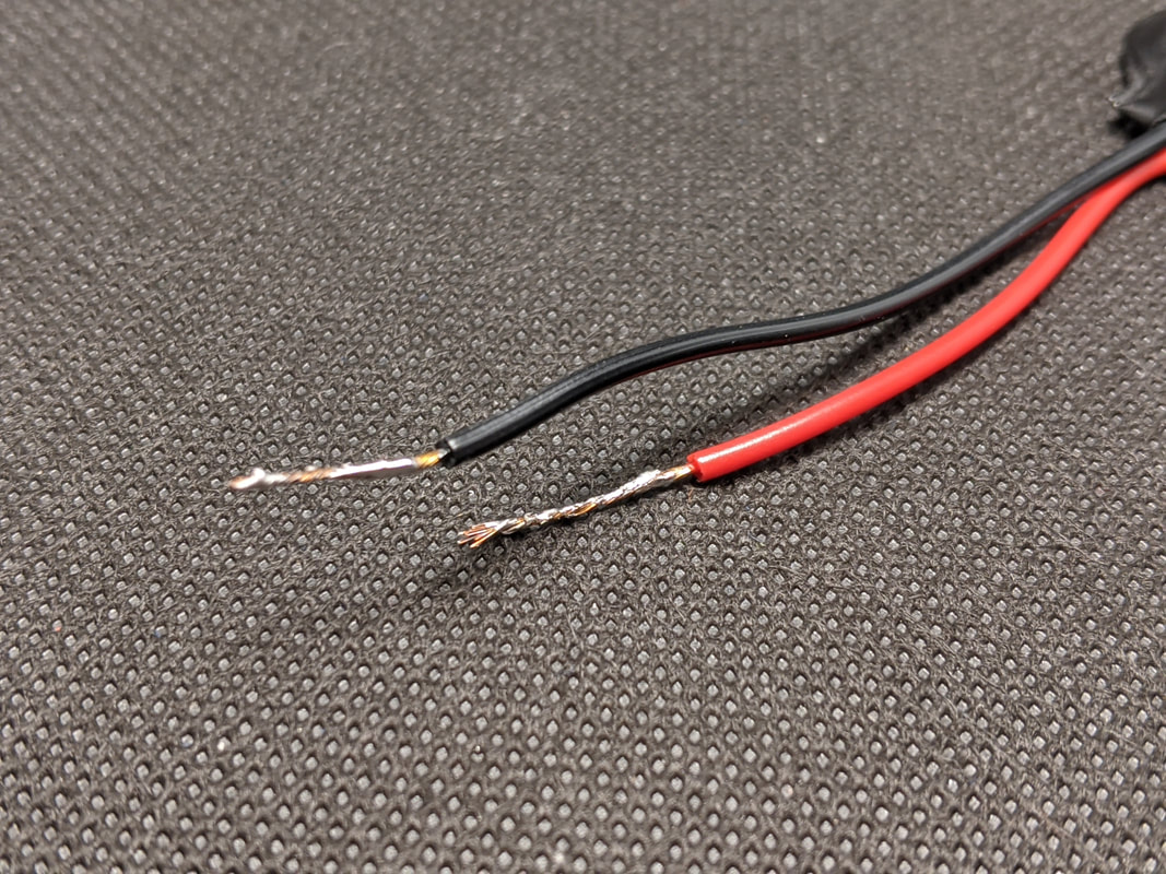
Alternative 2: Strip insulation and mount normally
If you have a pair of wire strippers, you can also strip back about 0.5 inches of insulation and tin the wires (i.e. twist the strands together and cover them in solder), then install it normally. If you do this, it is recommended that you put some glue or tape between the wires, so you do not short them!
If you have a pair of wire strippers, you can also strip back about 0.5 inches of insulation and tin the wires (i.e. twist the strands together and cover them in solder), then install it normally. If you do this, it is recommended that you put some glue or tape between the wires, so you do not short them!
|
|
|
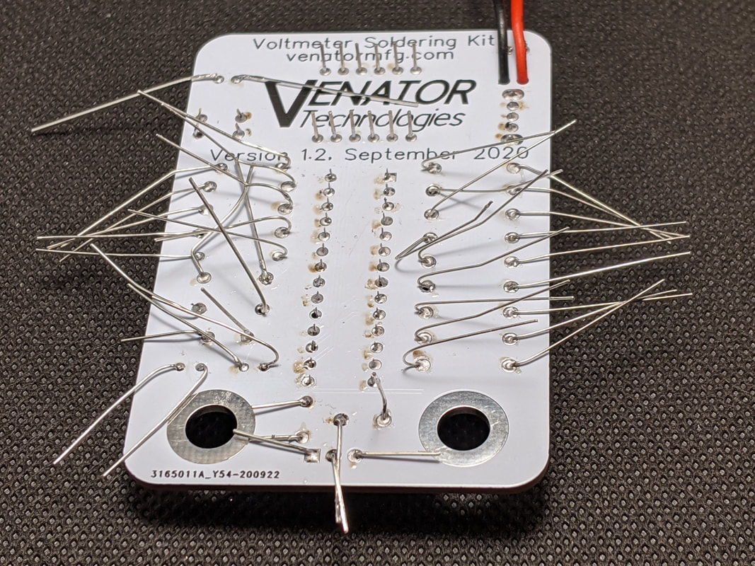
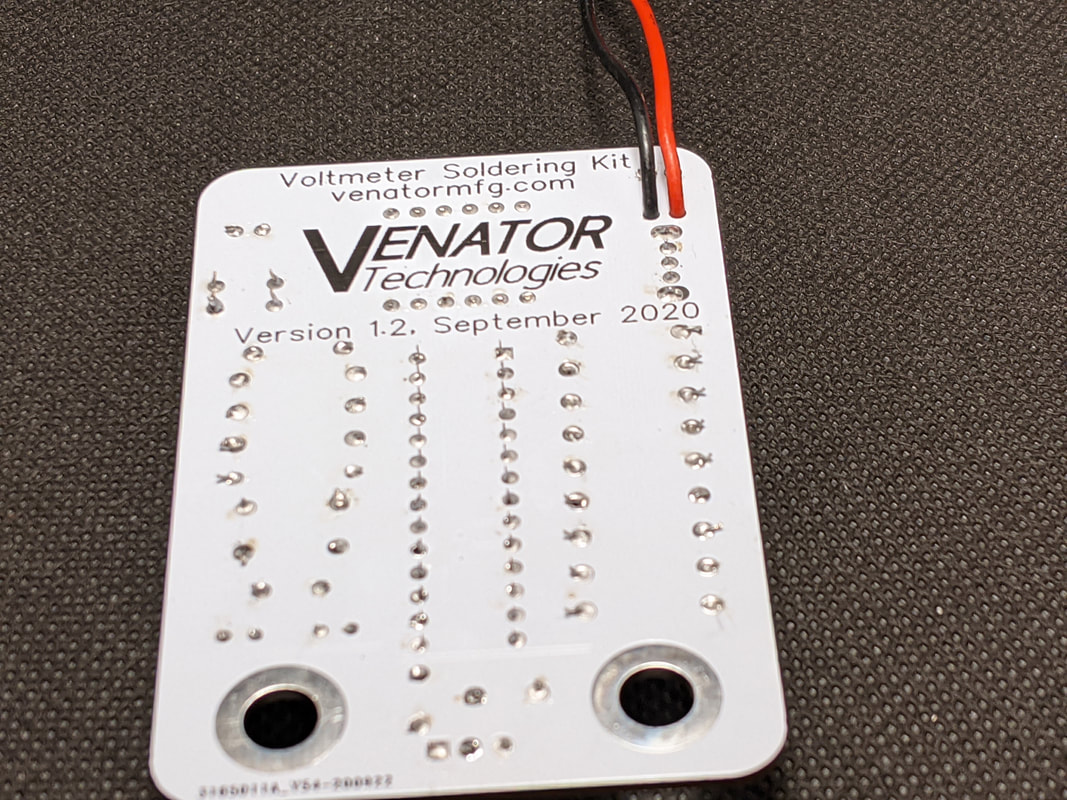
Step 15: Cleanup Leads
Trim the excess leads off the back of all the components, be sure not to cut too close or else you can damage the board!
|
|
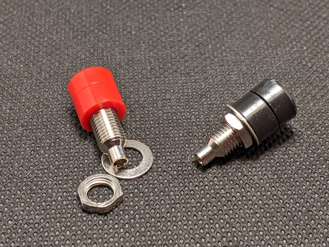
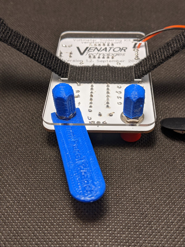
Step 16: Banana Jacks
Install the banana jacks from Bag 1 in the two large holes at the bottom of the board (red on the left, black on the right). The colored plastic piece should be on the top of the PCB, and the washer and nut on the bottom. Hand-tighten the nut for now.
|
|
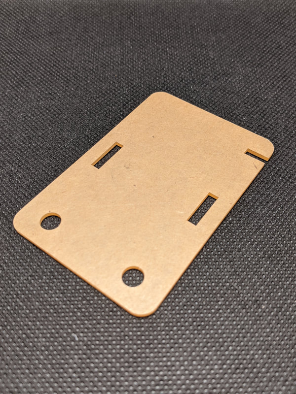
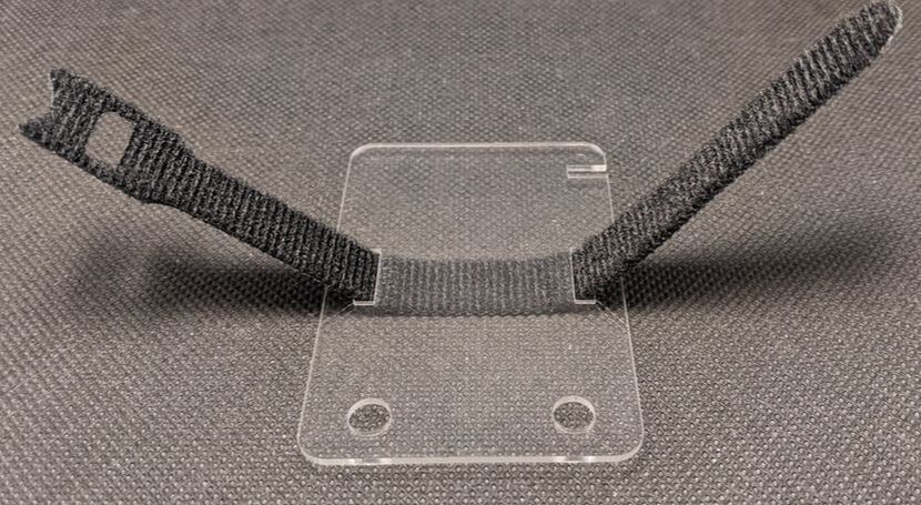
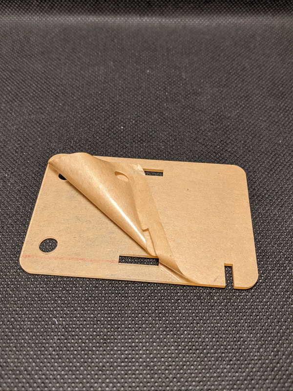
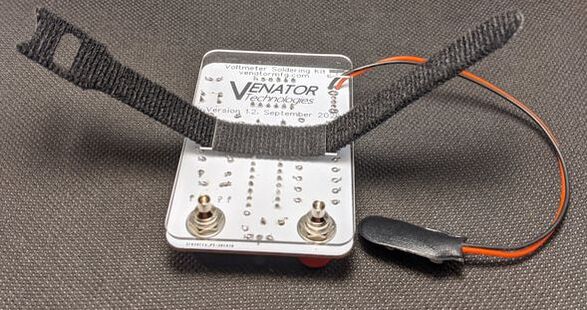
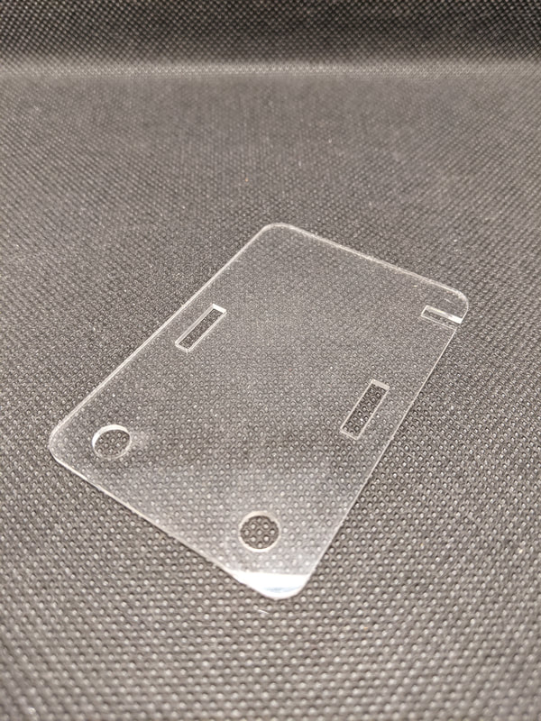
Step 17: Back Cover
Remove the paper protective layer from both sides of the acrylic backing in Bag 3. Pull the velcro strap from Bag 2 through the acrylic back plate so that an equal amount is out of both holes. Place the acrylic back plate on the back of the PCB, so that the banana jack threads come out the two bottom holes, and the battery wires come out the top slot. While holding the top of each banana jack, screw on a plastic protective cap to the back. Once the protective cap is on, use the panel wrench from Bag 1 to fully tighten the nut, while holding on to the top of the banana jack. When fully tightened, the top of the banana jack should not move. Finally, re-check the protective caps to make sure they are snug.
|
|
|